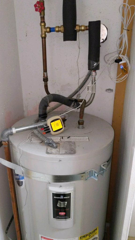
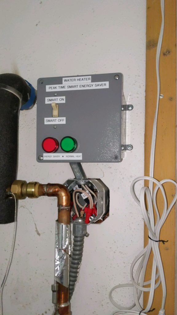
I’ve been wanting to save some electricity on my conventional electric hot water heater. Well, ok, that would be nice, but really I’ve been wanting to save some money on it. I recently found out that I could switch my power company billing to Time-of-Use, which has highest cost during certain periods of the day, and lower cost the rest of the time. I decided to build a smart control to shut off the water heater during the peak period.
I installed a thermostatic mixing valve, so I could turn up the tank temperature to ludicrous heat (150F/65C). It automatically mixes in cold water to keep the house pipes at a safe temperature (120F/50C). This gives me more total heat capacity in the tank.
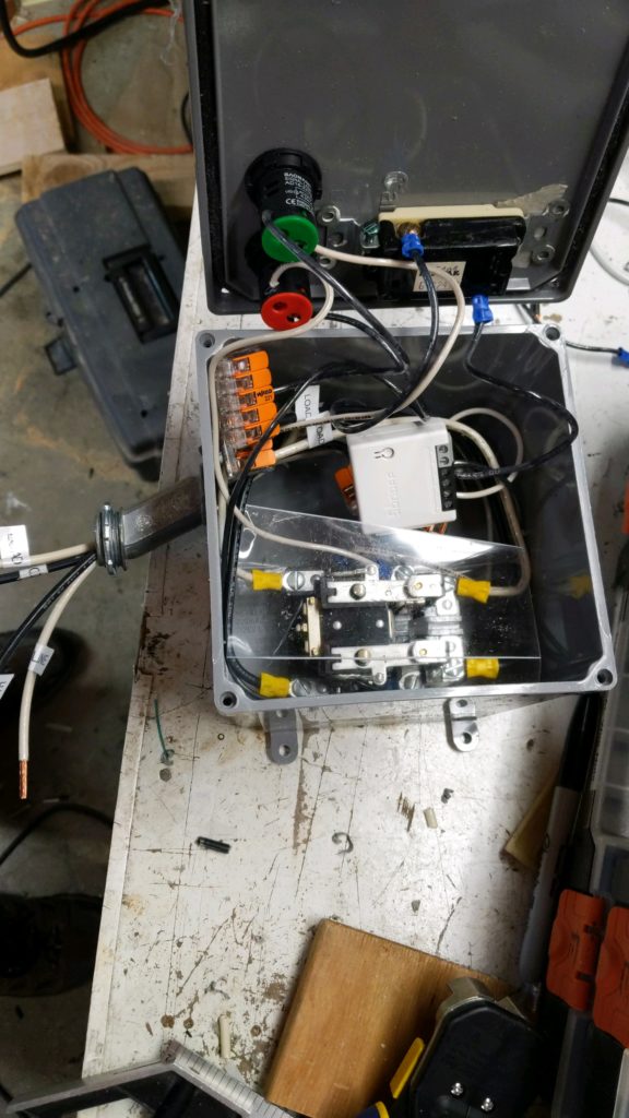
To monitor everything, I bought a Nutrichef 4-probe thermometer that broadcasts on bluetooth to Home Assistant (ESPHome BLE proxy). I put the probes on the upper half of the tank, lower half of tank, output pipe before mixing valve, and output pipe after mixing valve. I connected a 3V power supply into the battery leads (and kept the two AA batteries in parallel so it even has its own UPS haha).
The hours and time of day for peak billing vary by season of the year and weekday versus weekend, so I created a template sensor in HA that calculates what the current billing category is at any given moment.
My electrical switch is a 40 Amp contactor relay, controlled by a Sonoff ZBMINI Zigbee smart switch. The contactor is normally closed, so when it is not powered, the water heater operates normally. I turn on the smart switch to pull open the contactor, which interrupts the electricity to the water heater, for peak-time bypass. (Water heater is on a 30A circuit breaker, and draws 17A when heating, so a 40A contactor has a large safety margin.)
Since I’m also monitoring the bluetooth thermometers, if the tank temp drops too low during peak time, my automation will let the water heater operate and heat back up for a limited time. This way I ensure nobody in the house runs out of hot water, but a full tank reheat will wait until peak time is over. (So far this scenario hasn’t happened yet; tank storage has been enough to get through peak time).
I don’t know yet how much money this will save me, but I spent about $100 USD to put it together, which is a lot less than a new $1500 heat pump water heater.
It is also completely silent. I have not yet heard a heat pump water heater in person, but some reports say that they are loud. My water heater is in the center of the house, so noise is a concern.
This has now been in operation for about a week, and is working great so far. I’m waiting to see how next month’s power bill turns out.
I wanted to make some metal boxes and trays. I have plenty of scrap sheet metal from things like old PC cases and microwave ovens. I already built a sheet metal bending brake. Now I just need a way to fasten parts together. Something easier than drilling a bunch of holes and screwing or pop-riveting. Something less messy than soldering or glueing. Something where I can just magically zap the parts and have them stick together instantly. Eureka! Spot welding. Time to dig through Google. And the trash can.
initial assembly
The internet has lots of articles about how to make your own spot welder, so I’m not going to repeat everything here. The first article that inspired me was the spot welder on Hack-A-Day. There are plenty of other home made spot welder articles out there too.
Basic Design
The basic idea in spot welding is to send a high electrical current (amperage) through two pieces of sheet metal, which will heat them up enough to melt a little spot and stick them together (the “bead”). We produce the high current with a transformer, which changes high voltage low current from the wall outlet into low voltage high current in the work piece. The heat comes from electrical resistance. You need low resistance metals in your spot welder parts (copper and aluminum) so you can create heat in a higher resistance metal (steel). So this spot welder is really primarily for welding steel. Which is OK since that’s what the vast majority of scrap sheet metal is anyways. At least mine is. If you have access to some secret stash of cast-off titanium, you’ll have to figure that one out for yourself.
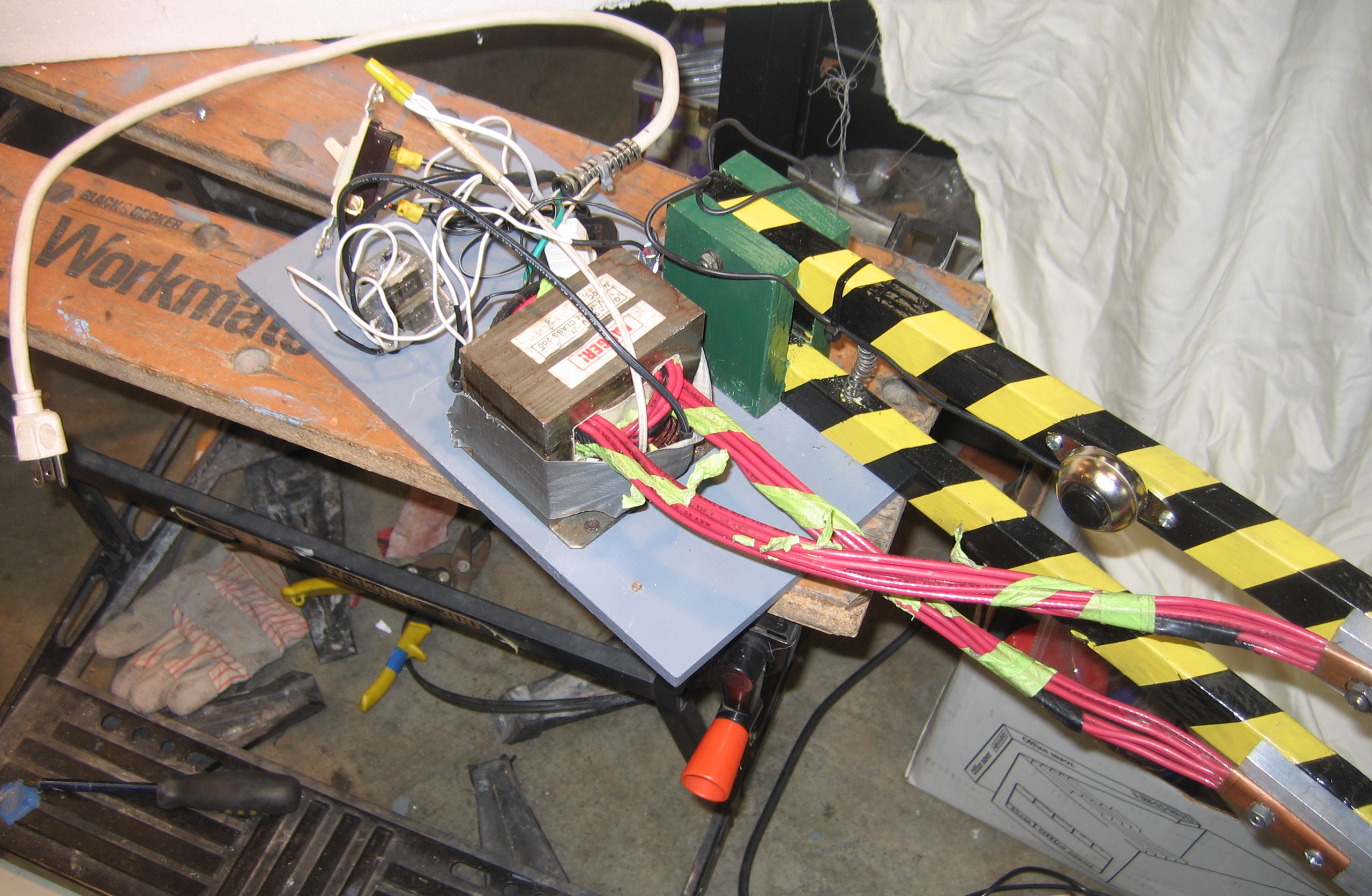
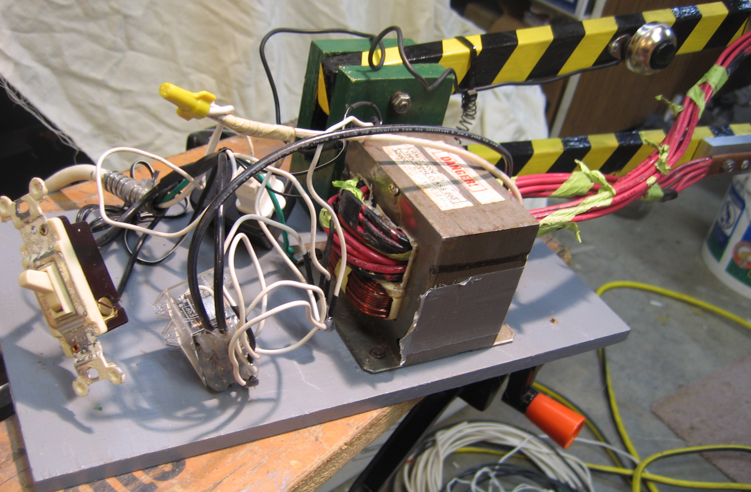
I needed a big, cheap transformer. Fortunately this is available in any discarded microwave oven. I can’t remember if my transformer came from the microwave oven left by the apartment dumpster, or the one left on the curb near the park. But you can probably find an unwanted, unloved microwave somewhere and give it new meaning for life. Or something like that.
Microwave ovens step up the voltage inside, but we want to step it down. So we remove the transformer secondary winding, with the lots and lots of turns of teeny-tiny little wire, and replace it with a few turns of big fat wire. I used a hack saw to cut off the old wire. You can try that or your teeth, but I’d recommend the hacksaw.
Wire size is dictated by the current, so we want as big a cross-section as possible in our wire. I used eight strands of 10-gauge (AWG) stranded copper wire, which the building electricians at work let me have when they were ripping out some old light fixtures. 10-gauge wire has a cross-section area of 5 mm sq., so that puts me at 40mm sq. for all eight strands. Those hot-shots in the other articles bragging about their 4-gauge wire? I got double the size. Oh yeah, who rules now, huh? HUH?!?! Oops, sorry, got carried away with the nerd contest there for a moment. Where was I?
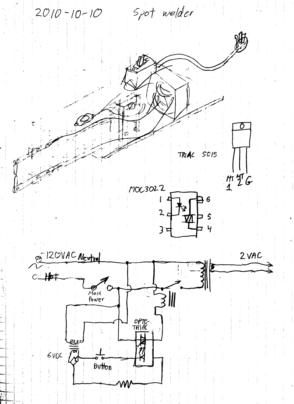
I wound one and a half turns of the wire, which was all I could fit. Measuring with my volt meter, I found that with 120 VAC input, I measured 2 volts on the output (open circuit with no load). When welding a bead, the 2 volts dropped to 0.5 volts. And the current? Using my inductive ammeter, I measured 15 amps on the input (mains) side, and 900 amps on the output side. Let me just say: it’s awesome.
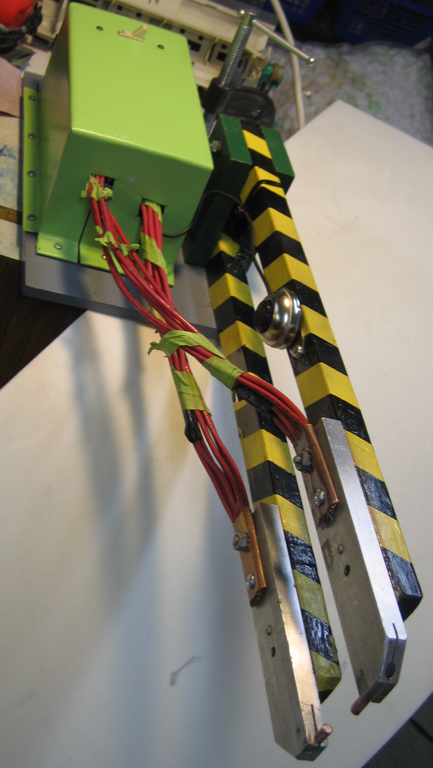
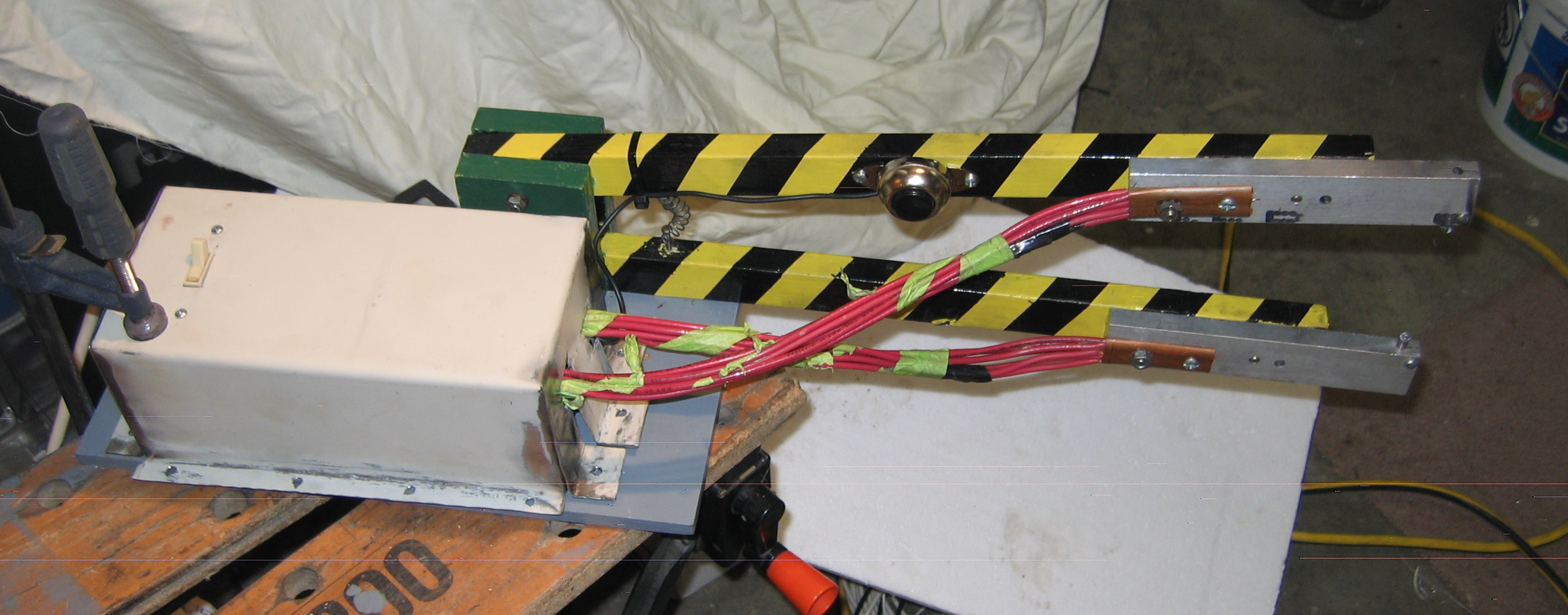
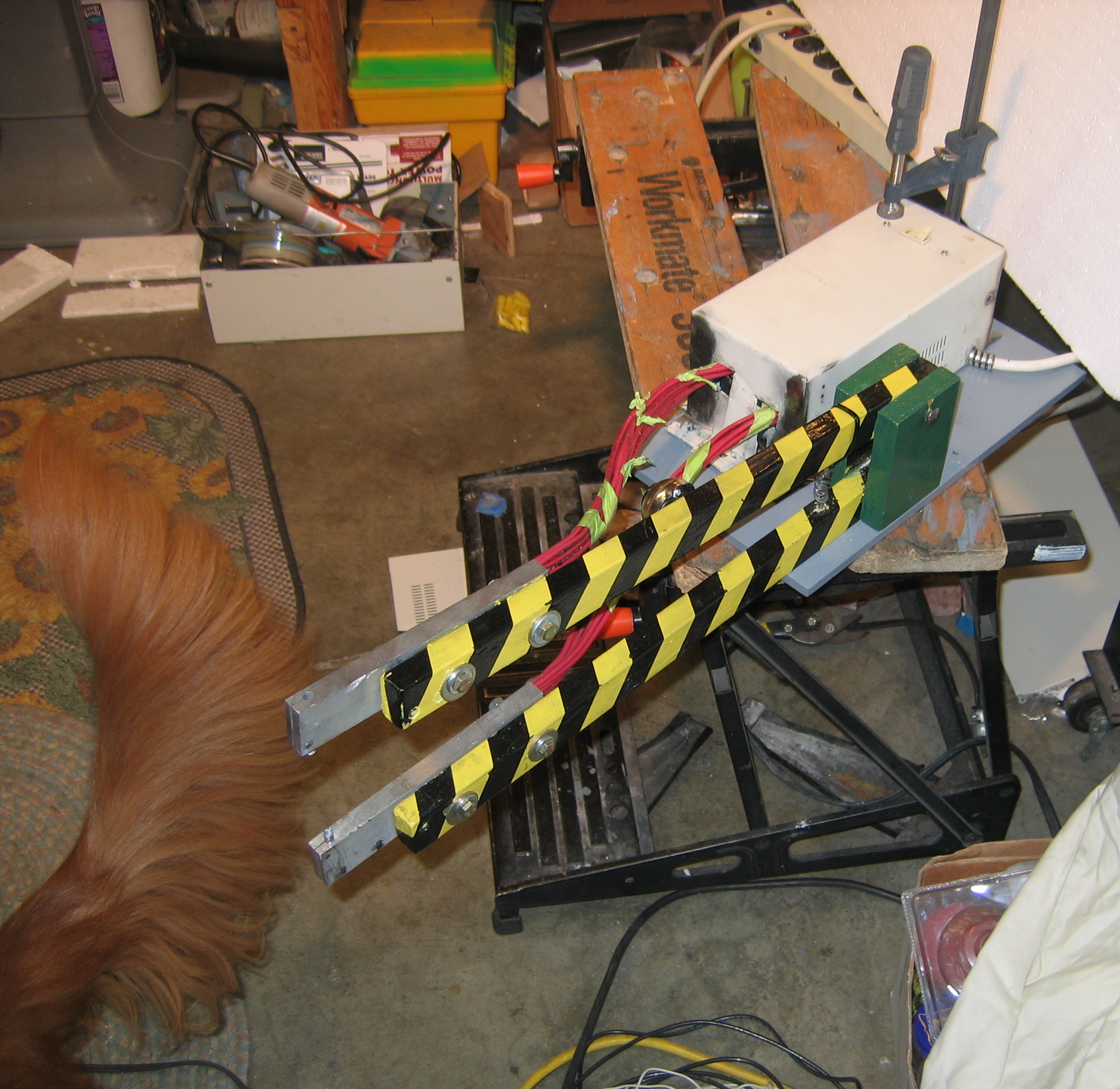
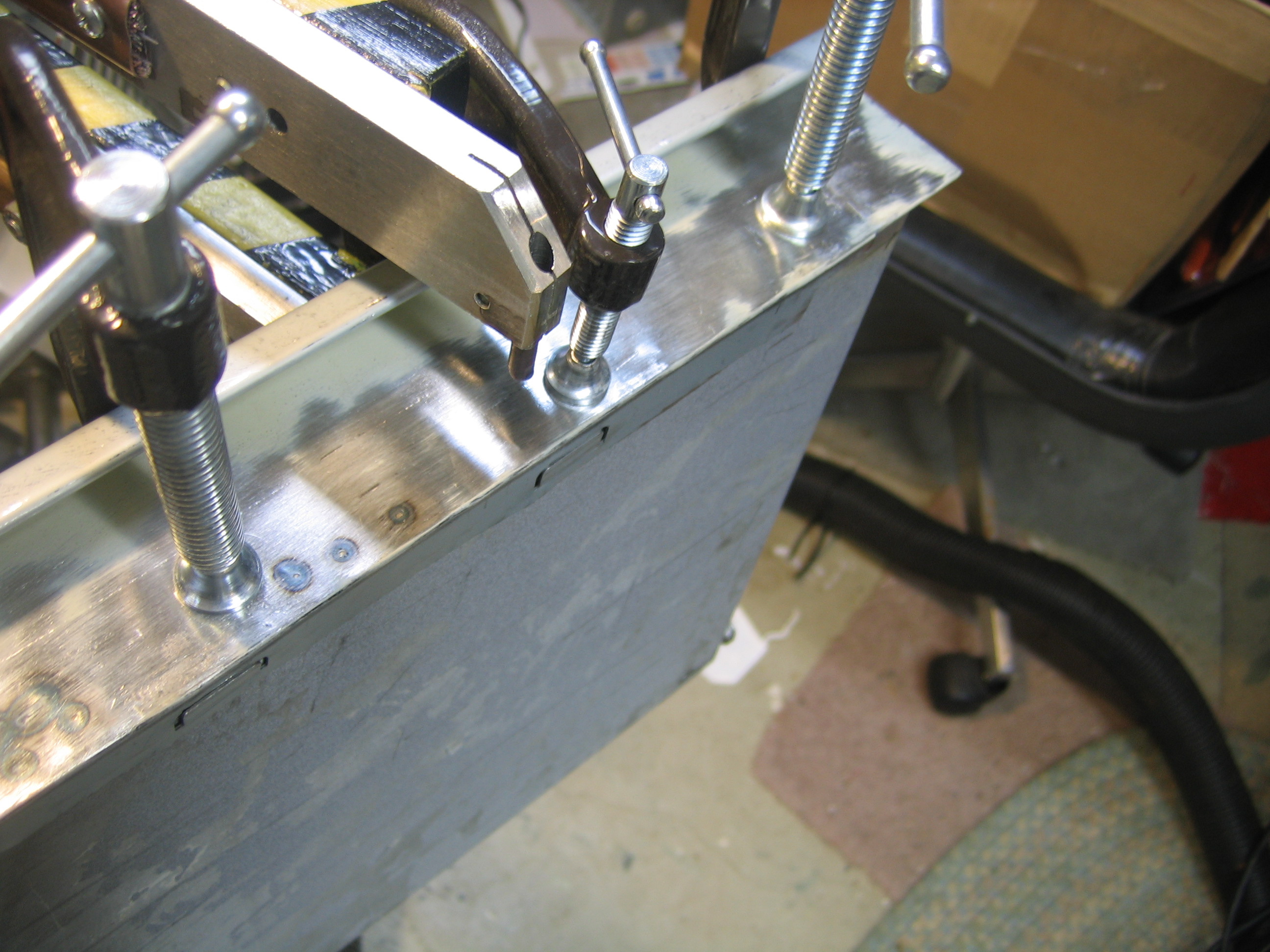
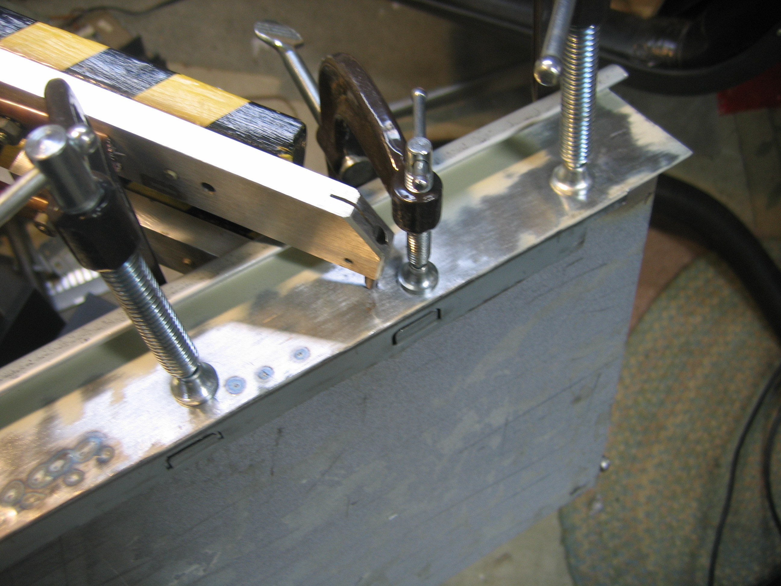
Mechanically, the design is simple. Two identical wooden arms held open by a spring. Each arm has an aluminum bar on the end, holding a copper electrode. The wire from the transformer is attached to the aluminum bar, with as much surface contact area as possible. I stripped the ends of the wires and smashed, I mean crimped, a piece of copper plumbing pipe onto the end to make a lug, and bolted it to the bar. (Actually, the first time I squeezed the pipe so tight that the side split open. The second time I got it tight enough to hold on to the wire but not split apart. No, that wasn’t admitting a mistake, that was a “design revision”. Yeah, that’s my story, yeah…)
The electrode tips are MIG welding tips, which are adequate although possibly a little short, depending on what you are doing. But they are inexpensive, which you probably know by now is one of my top criteria.
jaws and electrodes
jaws and electrodes
jaws and electrodes
My control circuit
internals
schematic
I needed a push-button switch on the upper arm, because I am all about elegance and comfort. Hold the arm down on the work piece, push the button until the acrid burning paint smoke burns my nostrils, I mean until the spot weld bead is formed, release the button, and then release the arm. (Just kidding on the smoke part; I always clean the weld area thoroughly to remove paint and contamination before attempting to weld it. Well, usually.)
internals
As far as safety goes, the spot welder is pretty safe. At a few volts, there is no concern of electrocution on the secondary output side of the transformer, the arms or electrodes. The main concern there is burning yourself on a hot piece of metal.
The primary input side of the transformer is another story. This thing works from 120VAC electrical mains, and I’m building it myself (that should scare you enough right there), so yes I’m a little leery about having high voltage right next to my finger on the push-button. My solution was to use a low-voltage control circuit. The push button operates at 6 volts, and activates a mechanical relay, which switches the 120 volt input to the transformer. I used a common “wall-wart” power adapter to provide the 6 volts. There is also a master on-off switch, for extra safety.
One possible concern with using mechanical relays is that arcing of the contacts can cause pitting and deterioration over time. This can be reduced by using larger contacts (in relays with higher amperage ratings). It can also be reduced by using solid state relays, but those cost more than, like, one dollar, so they exceeded my budget for this project. Since I knew I was drawing about 15 amps on the input side, I wanted my relay switching to be rated for much more than that, for safety and longevity. I got two double-pole relays rated at 12 amps, and wired all 4 poles in parallel. This gave me 48 amps nominal rating, which is safely far beyond my expected usage of 15 amps.
I added one more minor complication to the control circuit. I did not have any mechanical relays with low-voltage (6 volt) coils and high-voltage (120 VAC) high amperage (10+ amps) contacts. The only relays I had with high-voltage contacts also had high voltage coils, so I used another transistor-like chip called a MOC3022 opto-triac to control the relay. The opto-triac takes a low voltage DC signal and switches a high voltage AC line. The switched high-voltage AC output of the opto-triac is very low current, so it is not adequate to switch the transformer directly, but it is perfectly fine for driving the relay coil. So the push button activates the opto-triac, the opto-triac activates the relay, and the relay activates the transformer. Why make it so complicated? Well, because it was really cheap. The opto-triac cost less than a dollar, and the relays were a dollar or so also. While a solid-state relay would have been nice, it would probably have cost about 30 dollars, which is about 29 dollars more than my budget for the project.
Case
case
With live, high-voltage electricity feeding the transformer and control circuit, the spot welder needs a case to cover those parts for safety. Having been suitably inspired by “Uncle Dave” Gingery to make my tools bootstrap themselves, I knew that my spot welder needed to make its own case. I cut and bent some scraps from a PC to make a cover for the transformer and wires. Then I used the spot welder to attach the end panel of the cover. Voila! The machine builds itself! Well, partly at least.
case (and my assistant Sam)
case
spot welded its own case
Results
This thing works fairly well. I’ve mostly been using it on some salvaged sheet metal from a refrigerator door, and from PC cases. The thinner refrigerator door skin welds a good bead in 1 or 2 seconds. It measures about 0.025 inches thick (about 0.6 mm, or perhaps 25 gauge I think). The heavier PC case metal takes about 4 or 5 seconds to make a good bead. It measures about 0.040 inches (about 1 mm or perhaps 19 or 20 gauge I think).
The tips and big wires get fairly hot in use. If I weld PC case metal for 5 minutes straight, I need to stop and let the spot welder cool down for another 5 or 10 minutes. The arms themselves are wood, and remain quite cool to the touch. Wood seems to be a pretty good heat insulator.
The first real project for the spot welder (not including making its own case) is attaching the drawer fronts of my tool-box-in-progress. I’ll finish it one of these days. In the mean time, I’m spot welding!
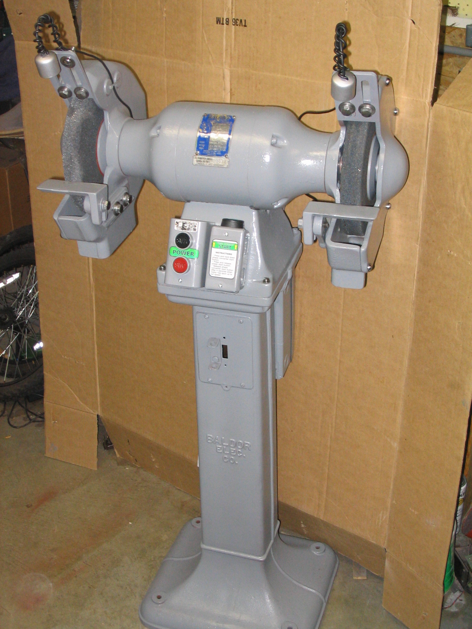
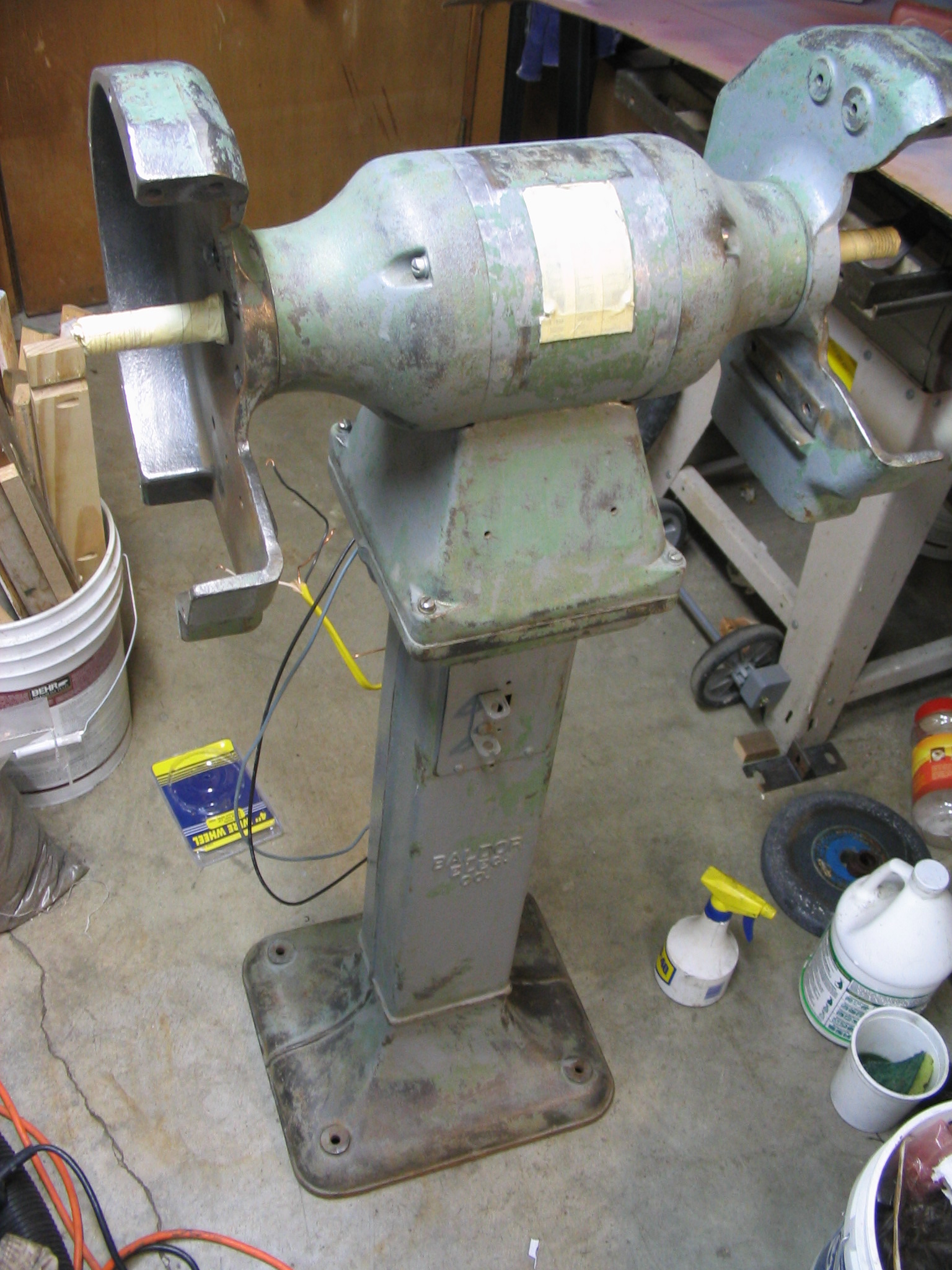
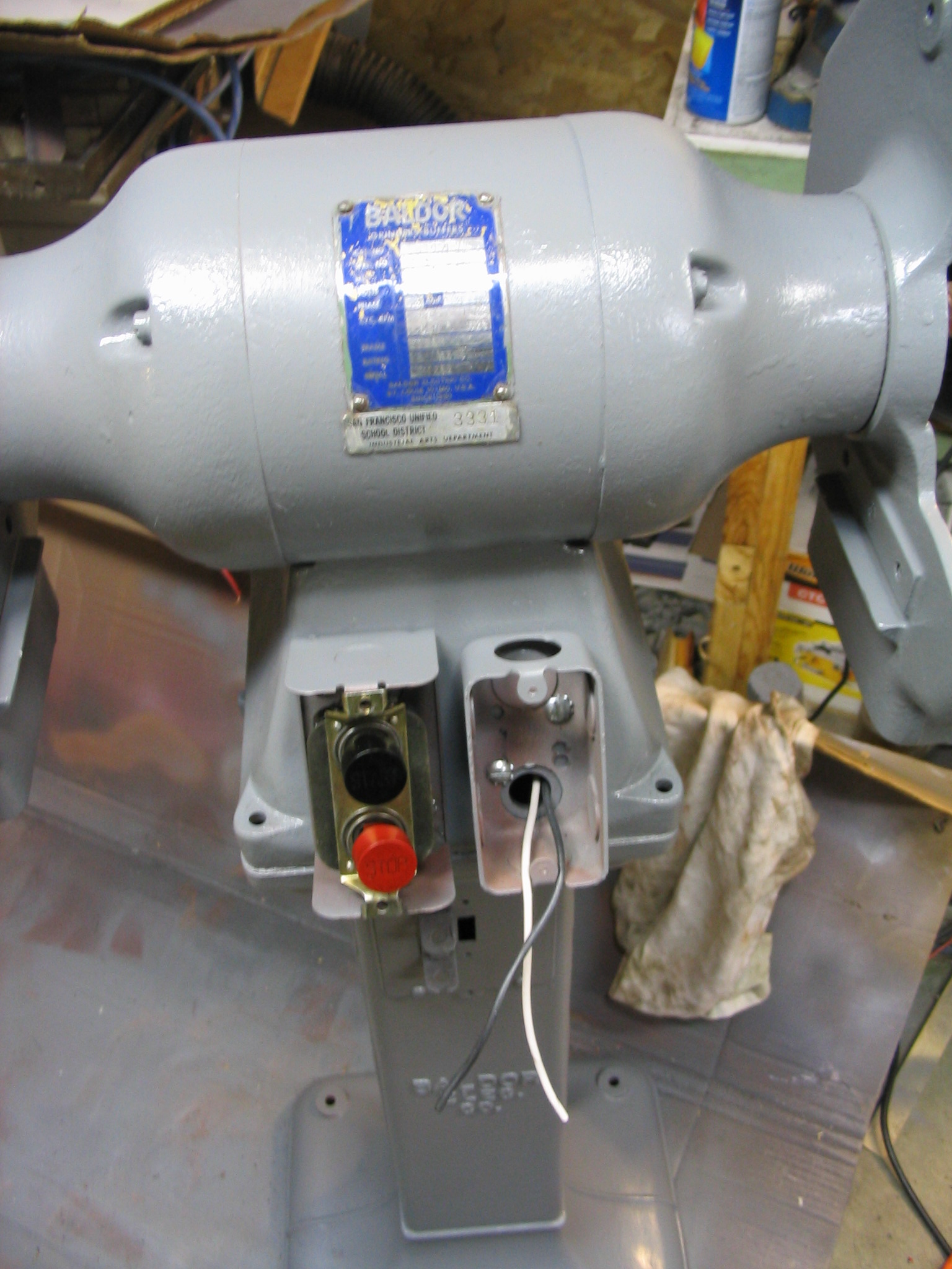
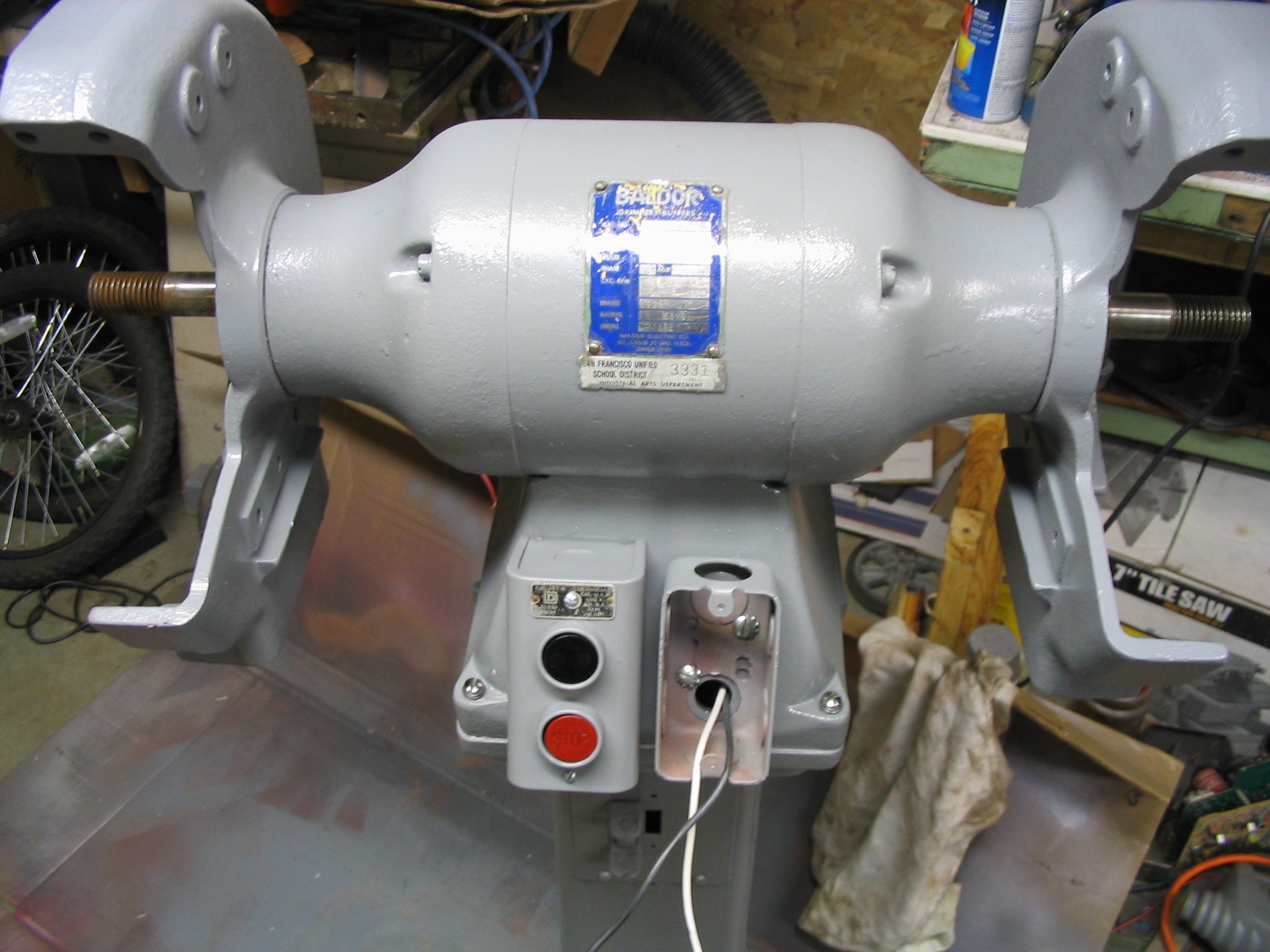
I received a Baldor metal grinder with 10-inch wheels, on its own pedestal floor stand, discarded from a school metal shop program. Several owners before me did not know what to do with it, mainly because the motor is wired for three-phase industrial power which is not found in U.S. residential homes. My job was to fix it up and get it working.
There were two major tasks to the restoration: cleaning/repainting, and making the three-phase motor work.
Cleaning and Painting
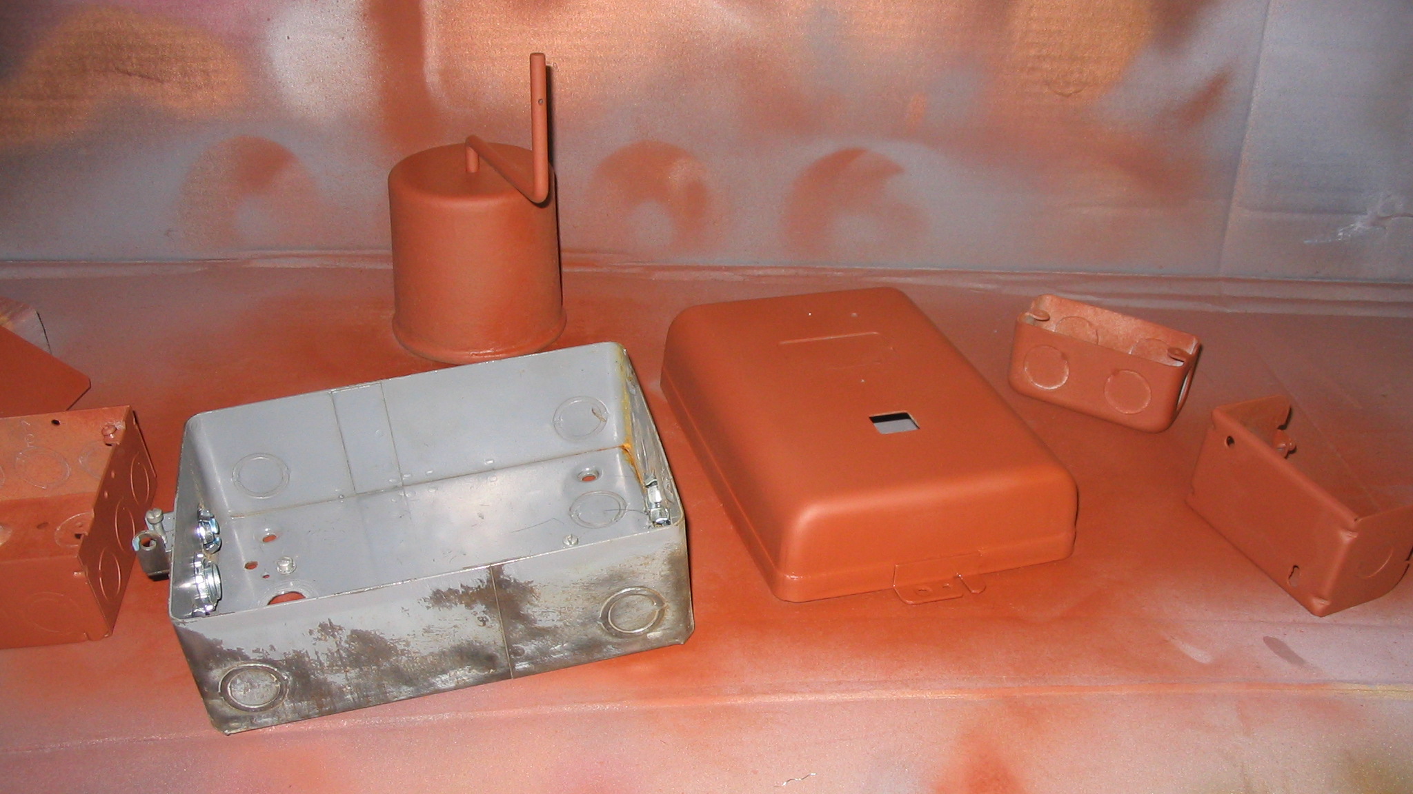
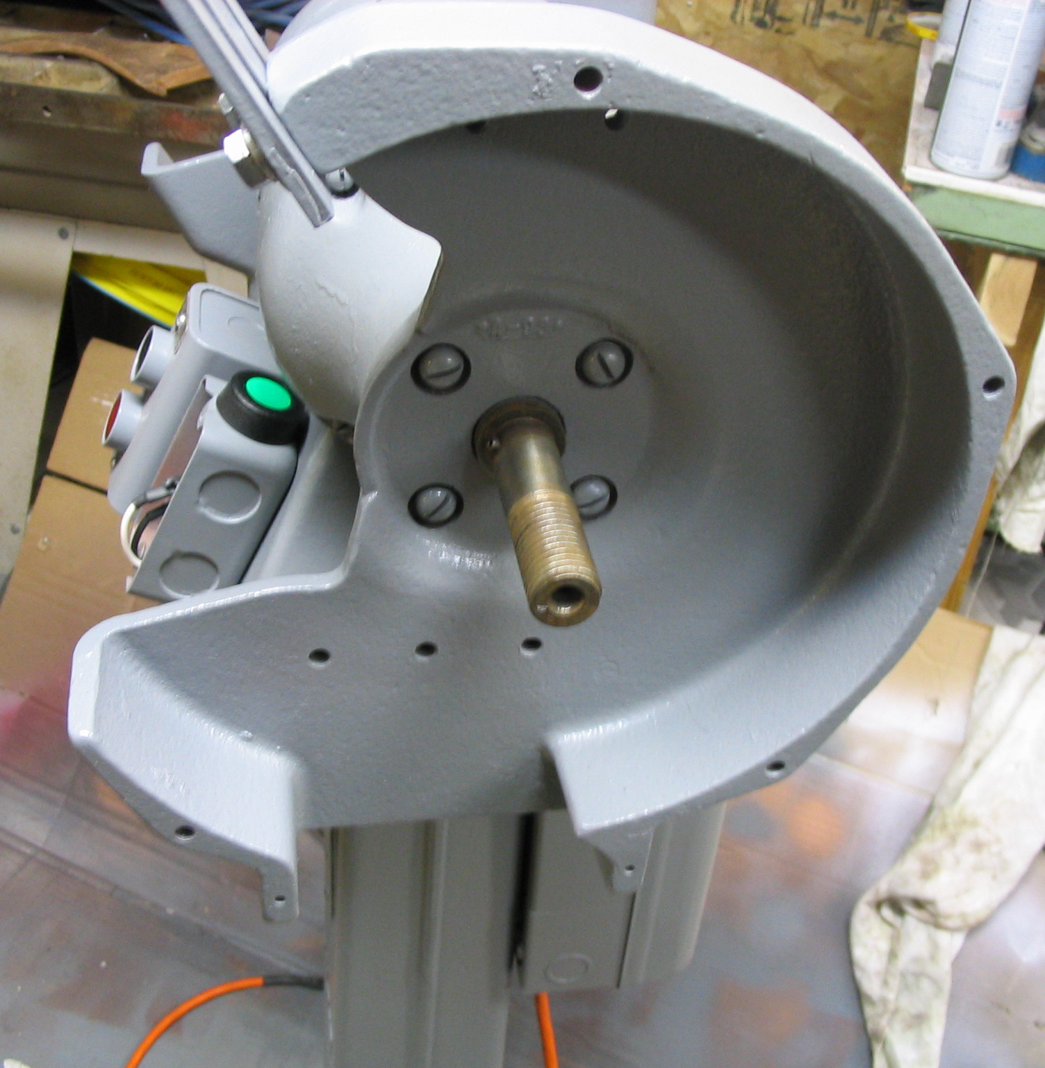
I started the cleaning process by removing all attachments that I could, including the wheel shroud side covers, the wheels themselves, and all electrical boxes and covers. I remove all of the old flaking paint and minor rust spots using a wire wheel brush on the electric drill. Some of the paint was still good, but much of it was stripped down to the bare metal. I could not remove the riveted-on motor label and didn’t want to paint the wheel axles, so I covered them with masking tape.
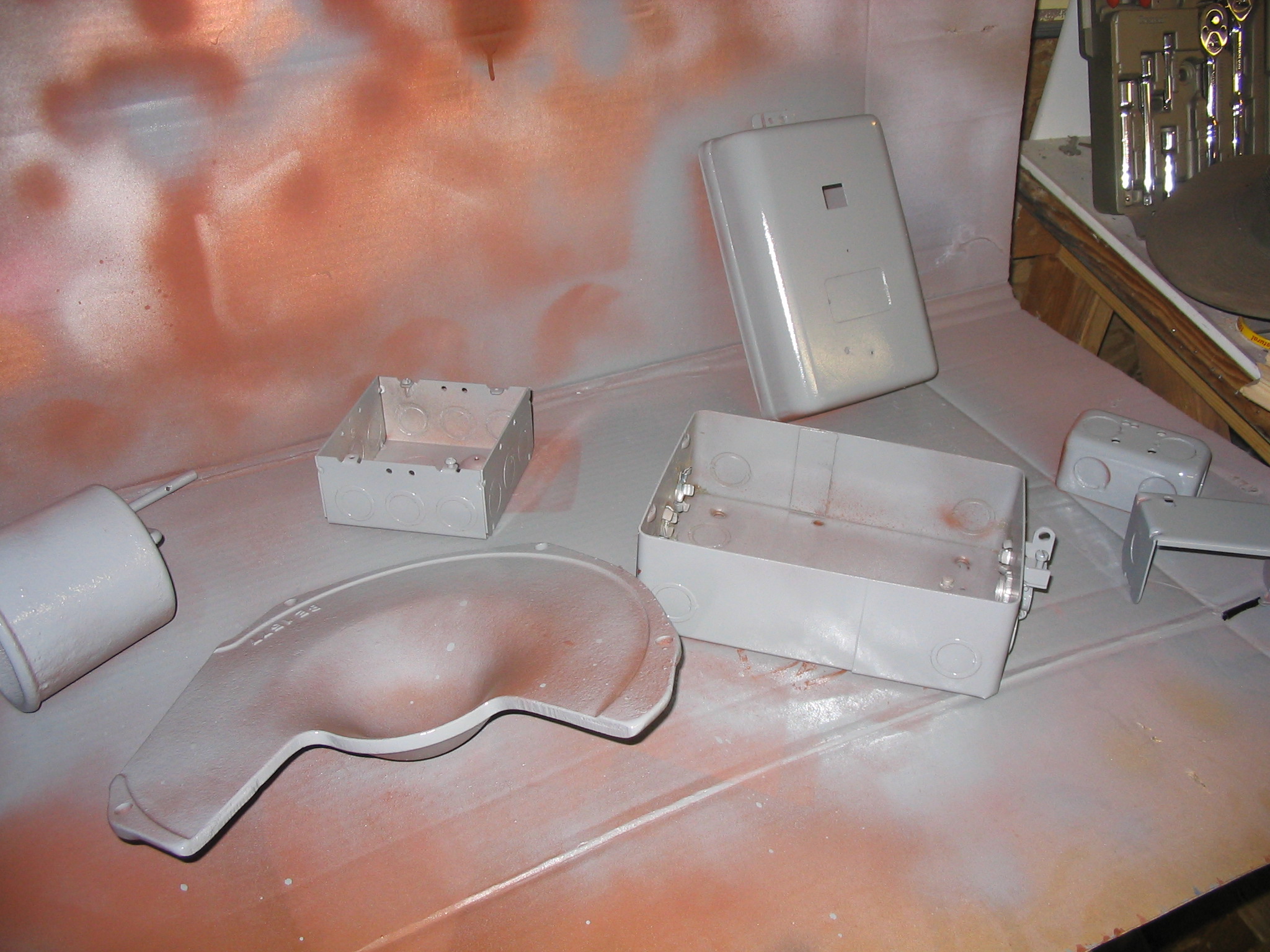
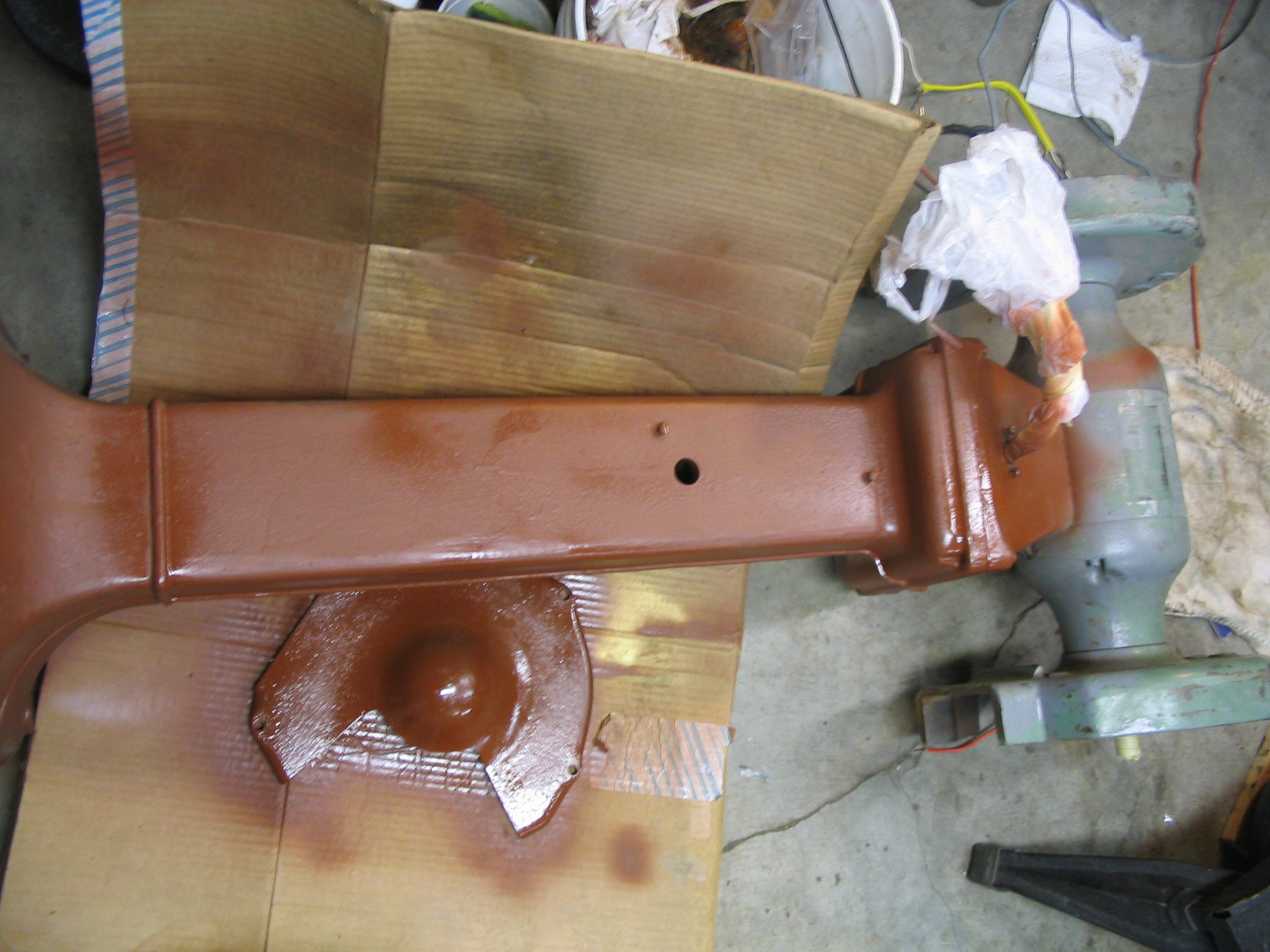
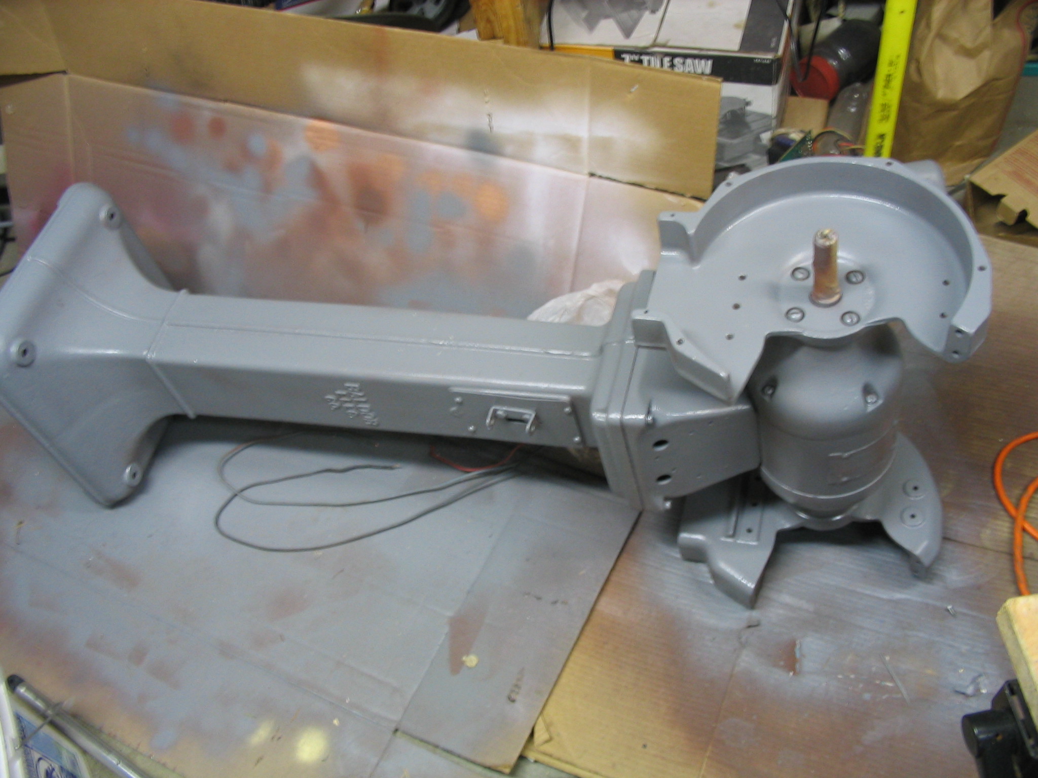
I spray painted the entire grinder and all the separate parts with primer for a good base coat. I followed it with a few coats of grey paint.
Stripping paint and rust
Priming parts
Painting parts
Priming body
Painting body
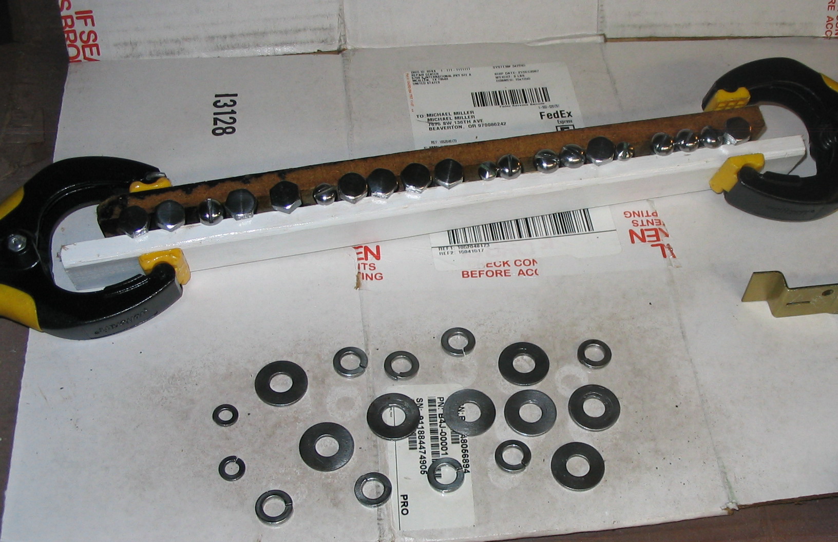
Polishing hardware
I cleaned up the hardware to make it look a little nicer. I filed and sanded the heads of the screws and bolts while spinning them in the drill press. I buffed all of them with a cloth wheel, which made them nice and shiny. I finished it with some clear spray varnish.
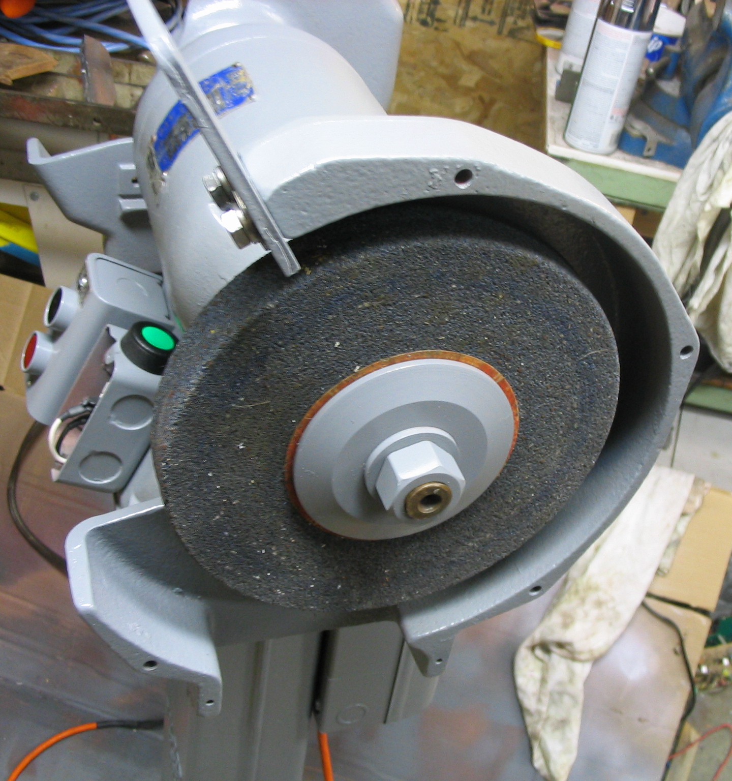
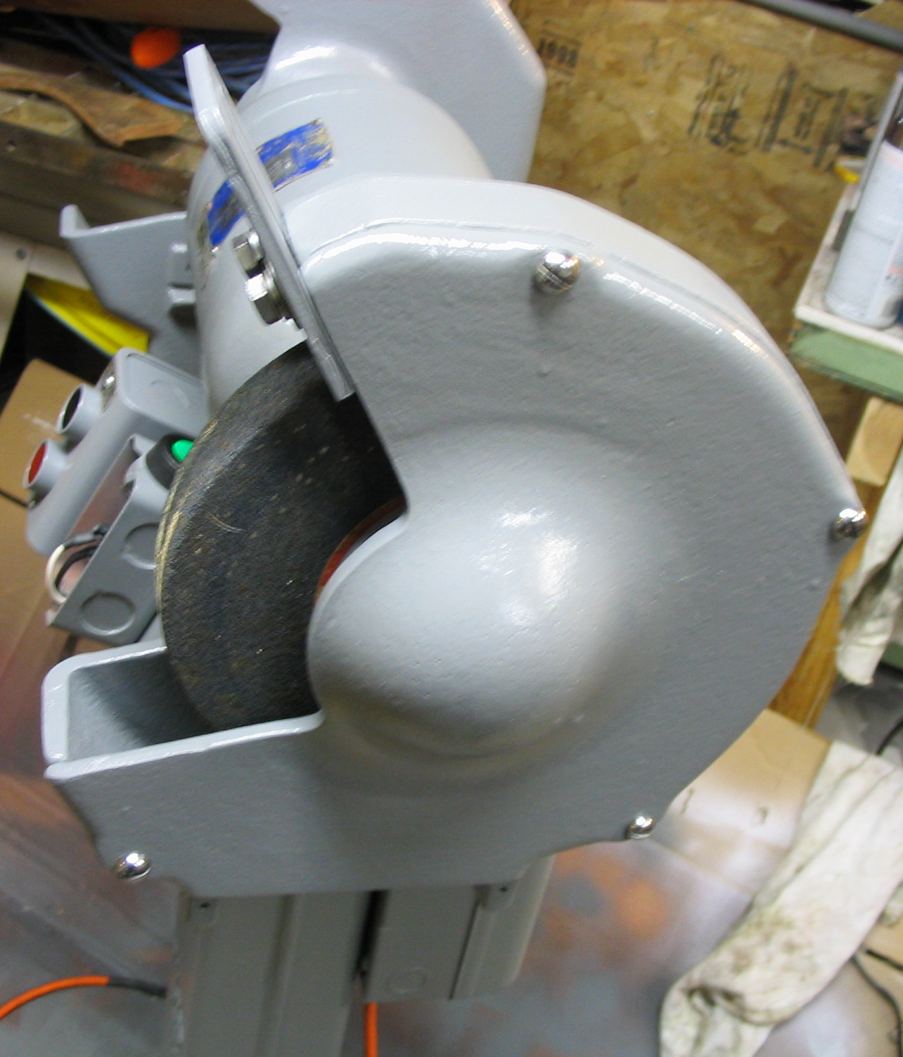
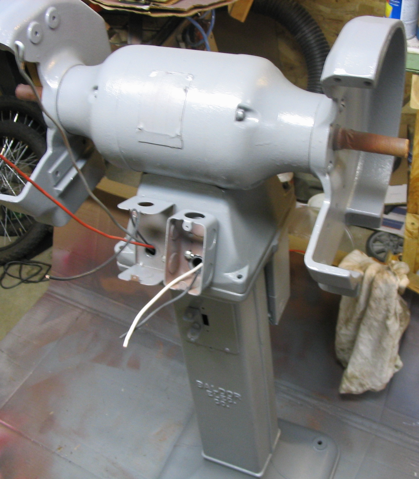
I reassembled all the pieces, back in the order they came off.
Painted well
wheel reinstalled
Shiny screws
Electrical
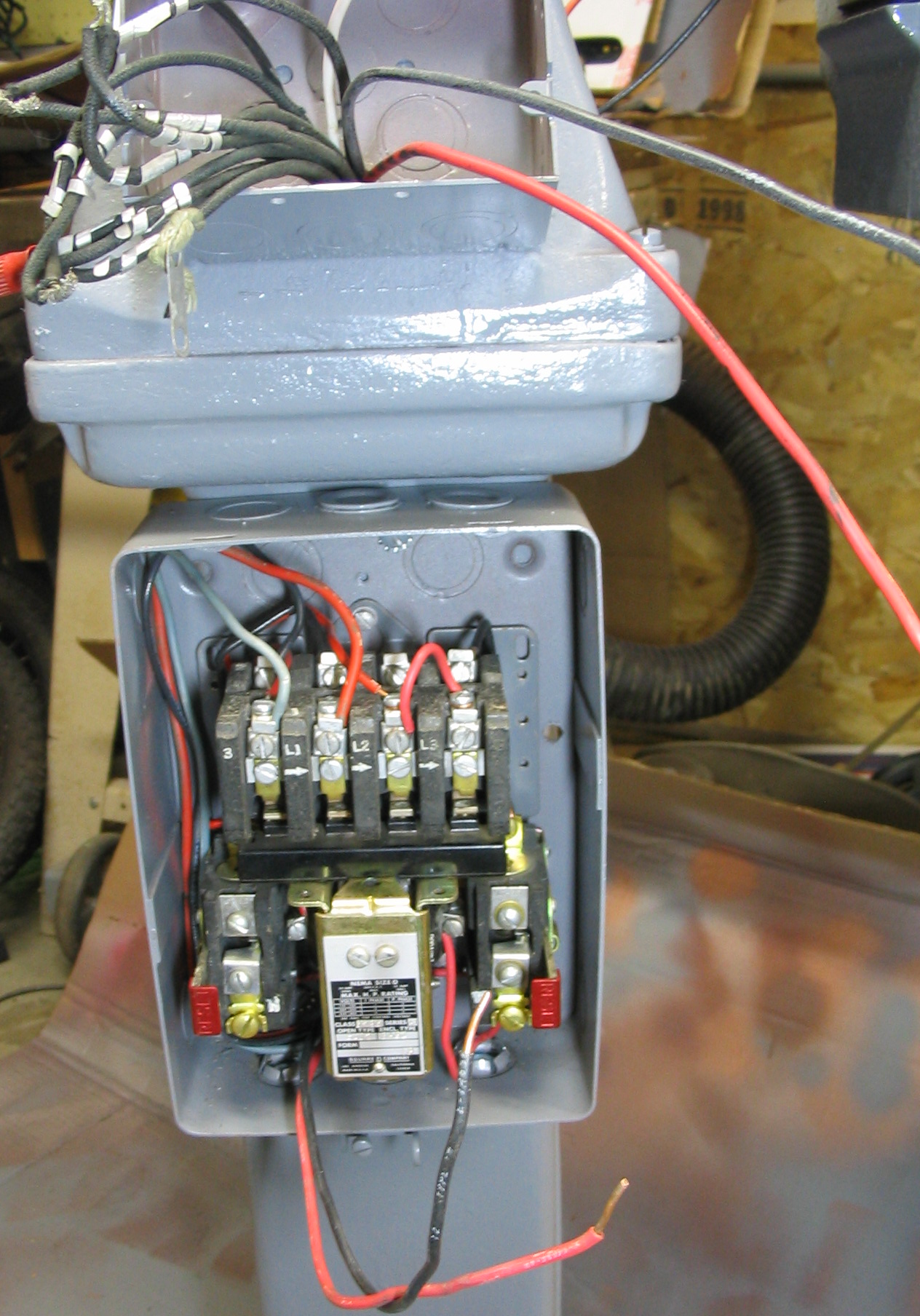
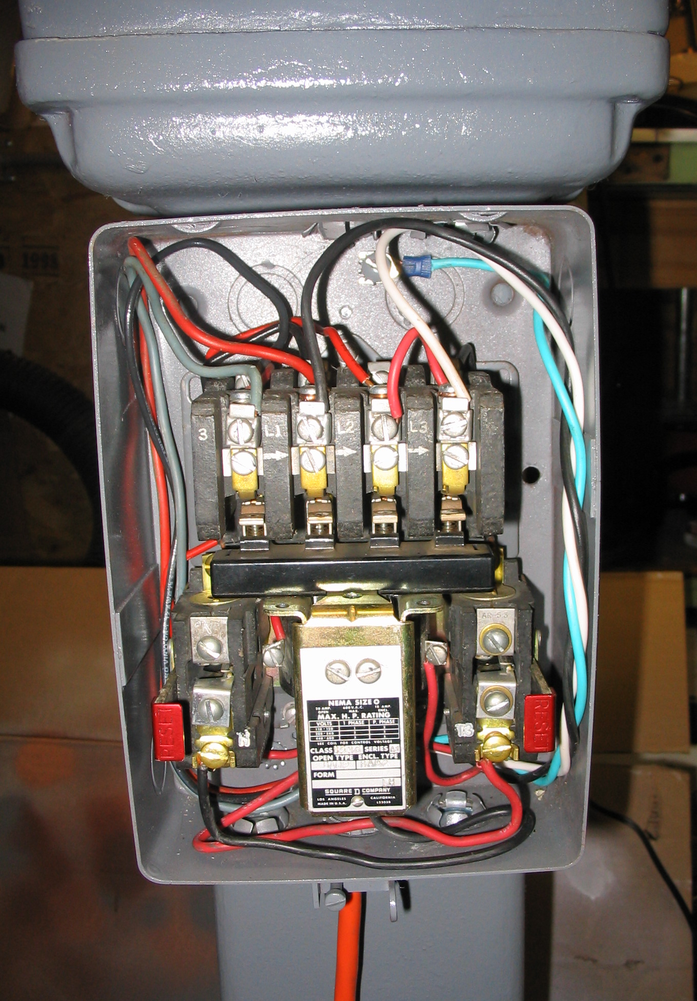
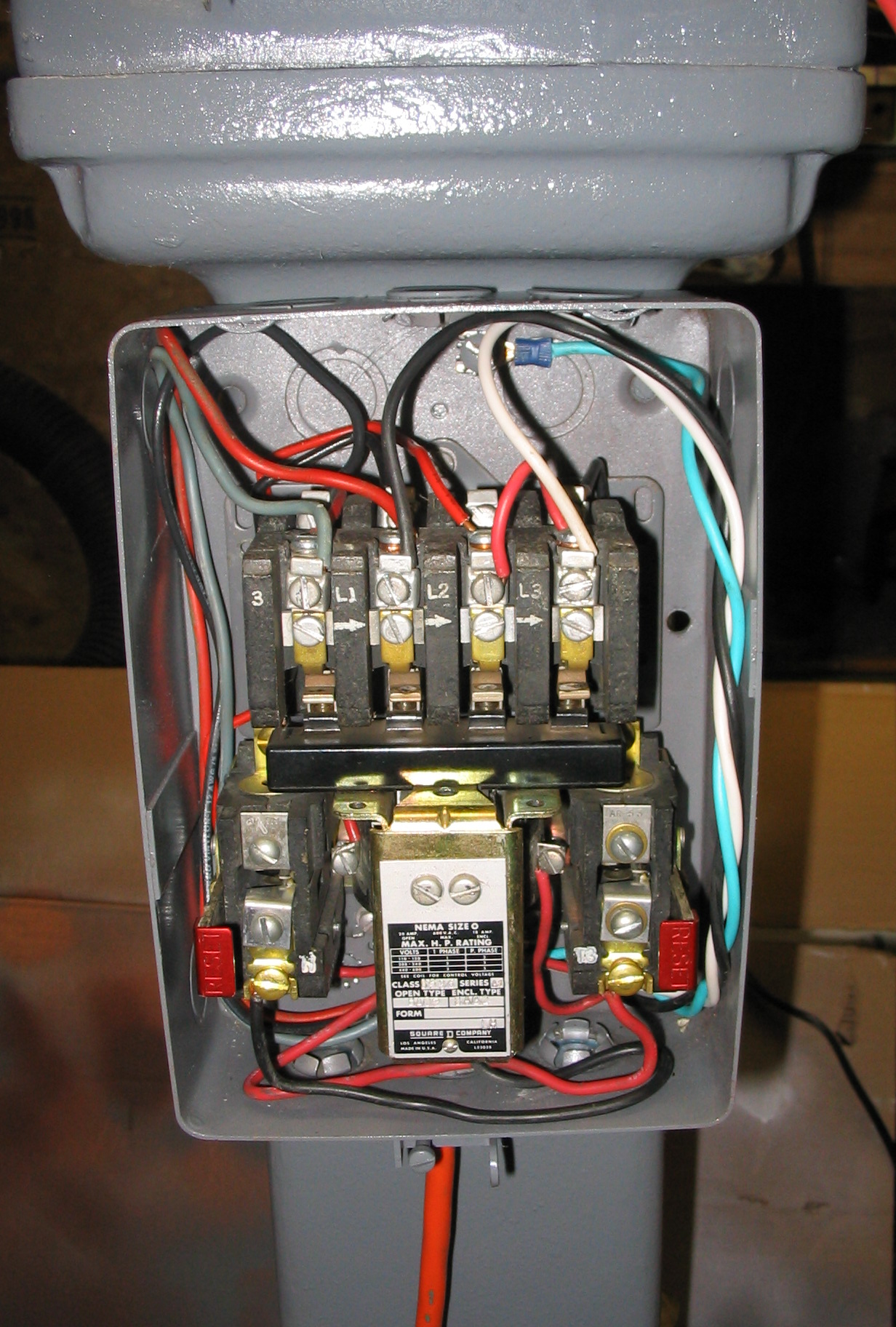
Originally this grinder was hard-wired to the wall using “BX”-style flex conduit. There was a power relay and circuit breaker box, which engaged and disconnected all three phases in sync, using start and stop push buttons.
For the 3-phase power, I built a
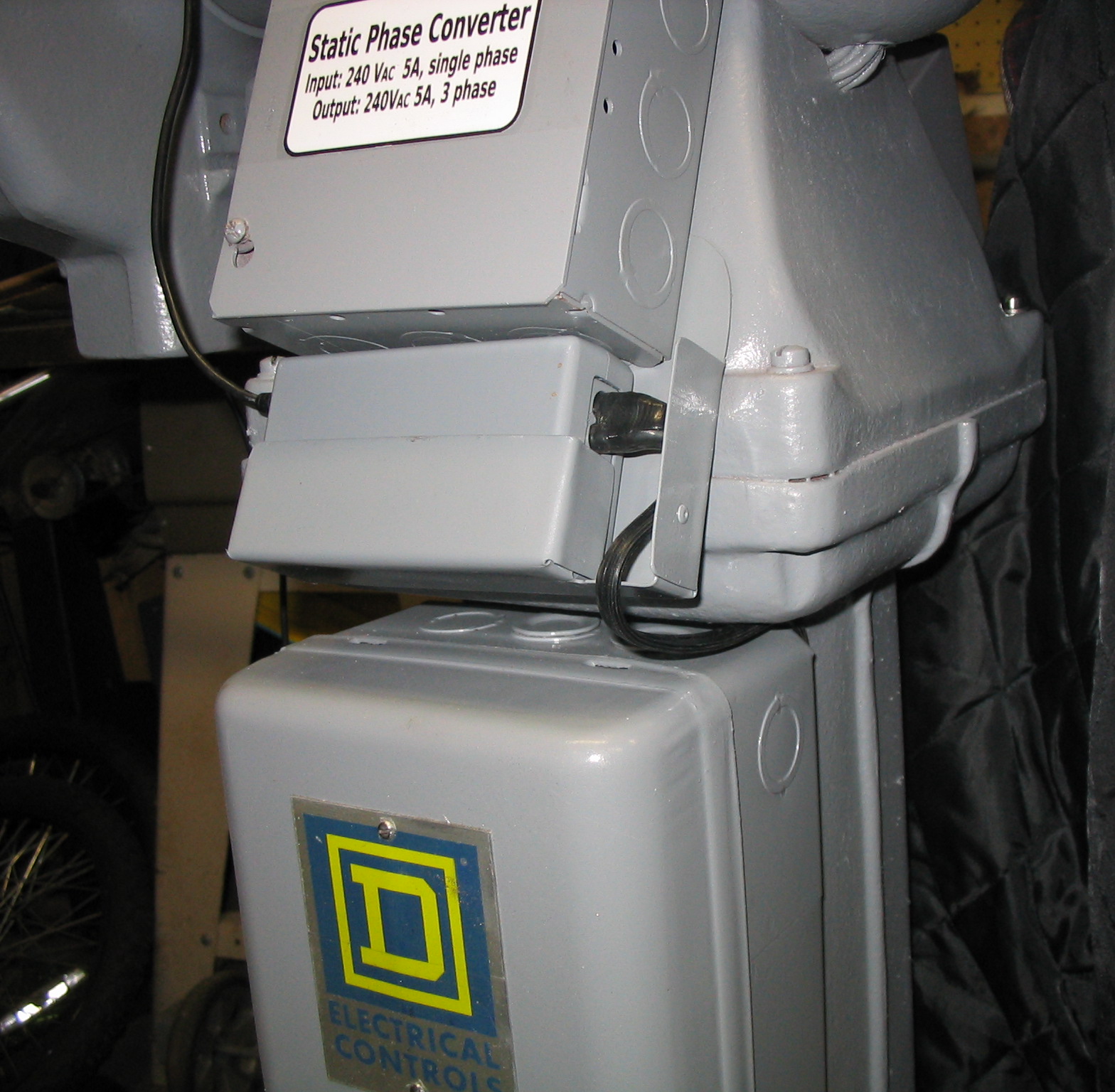
static phase converter using capacitors.
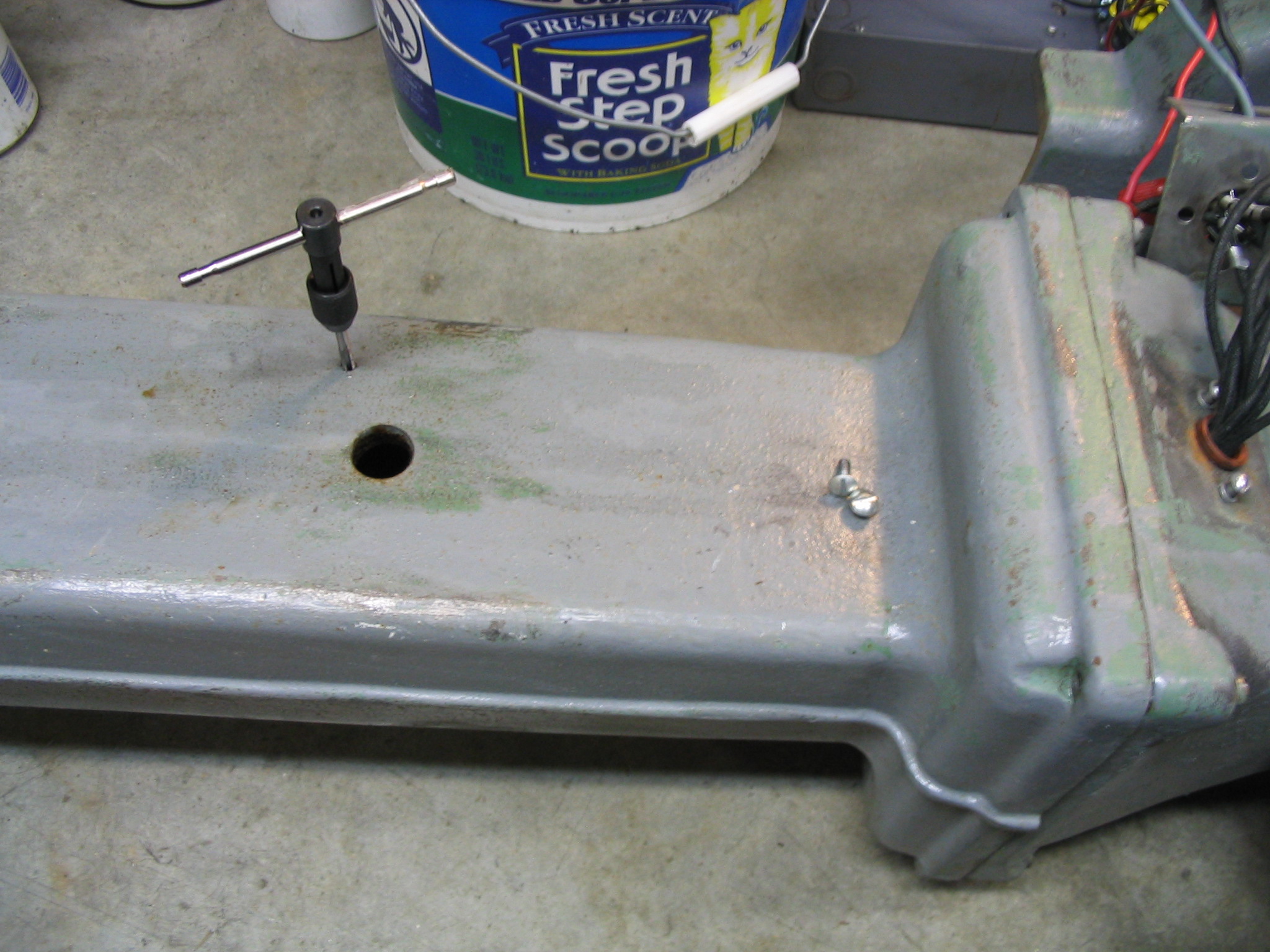
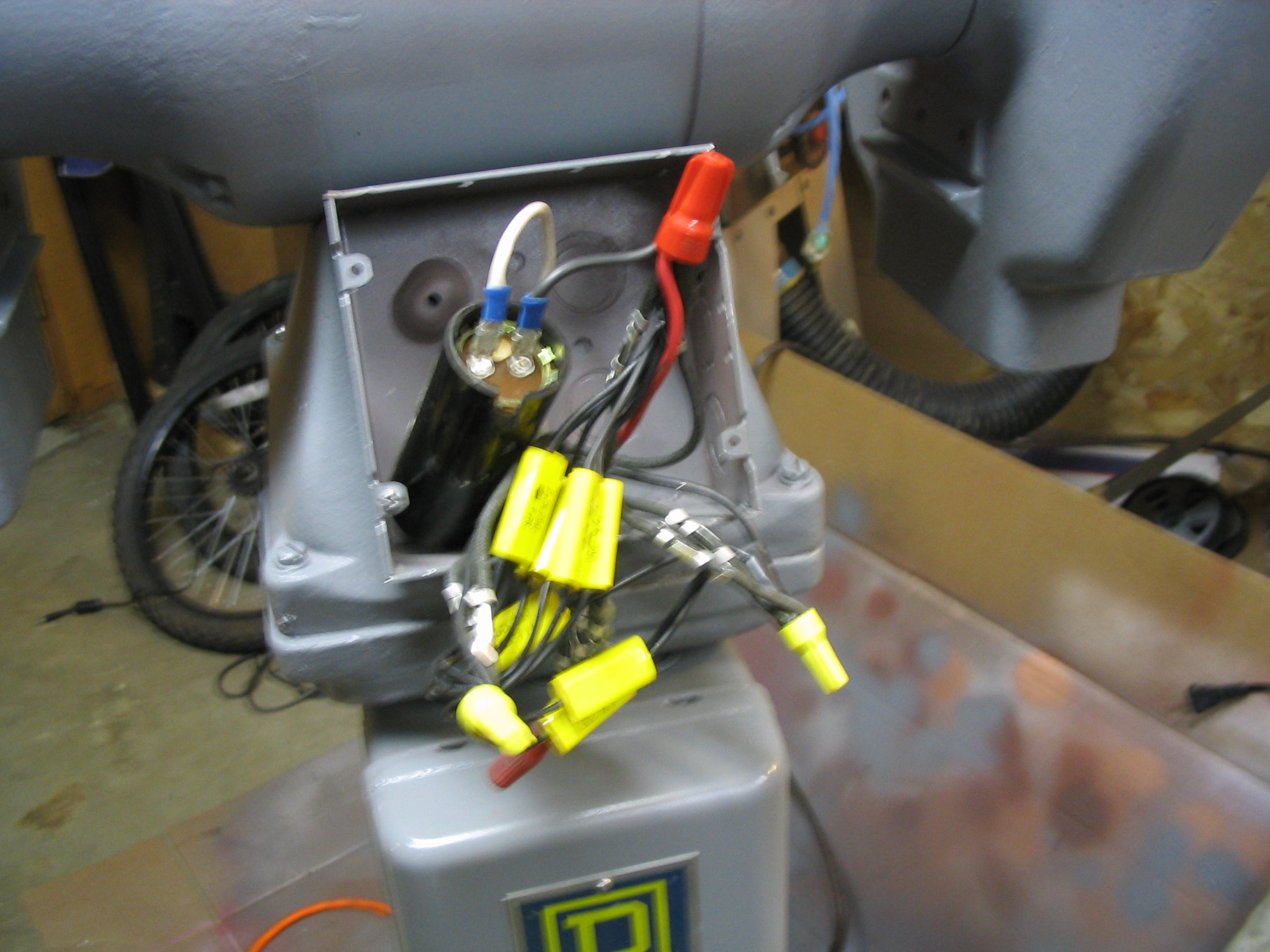
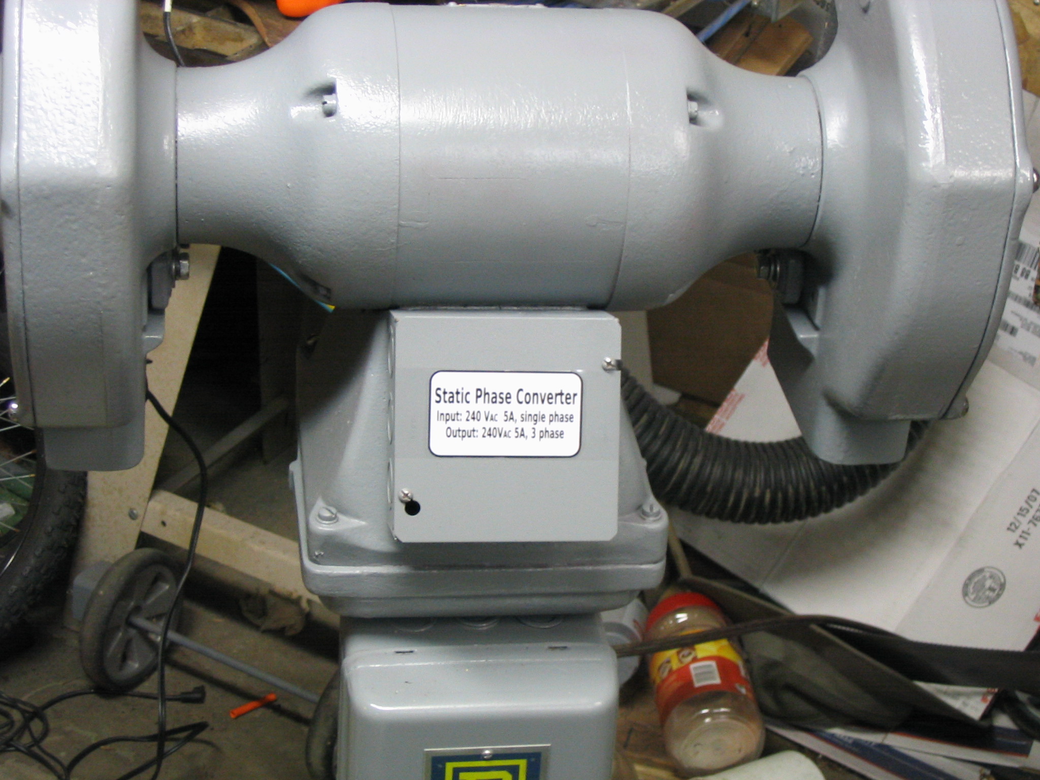
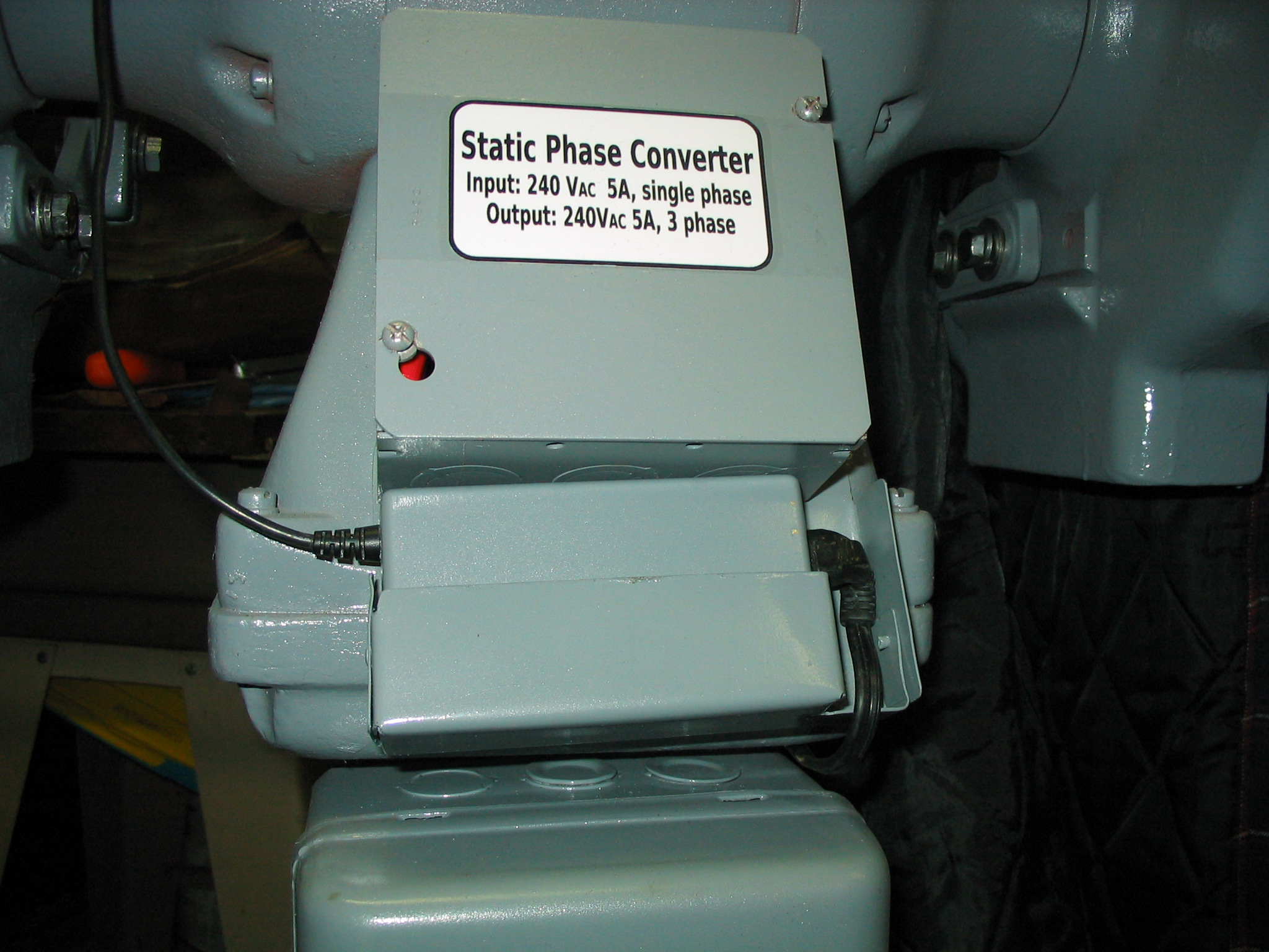
I rewired the relay box to supply single phase power to the phase converter. I attached it to the pedestal stand of the grinder. I drilled holes in the pedestal and tapped screw threads into them, and screwed the relay box in place. Instead of flex conduit for the power line, I added a standard power cord. Since it uses 240 volts, double the US standard, I used a different plug and outlet.
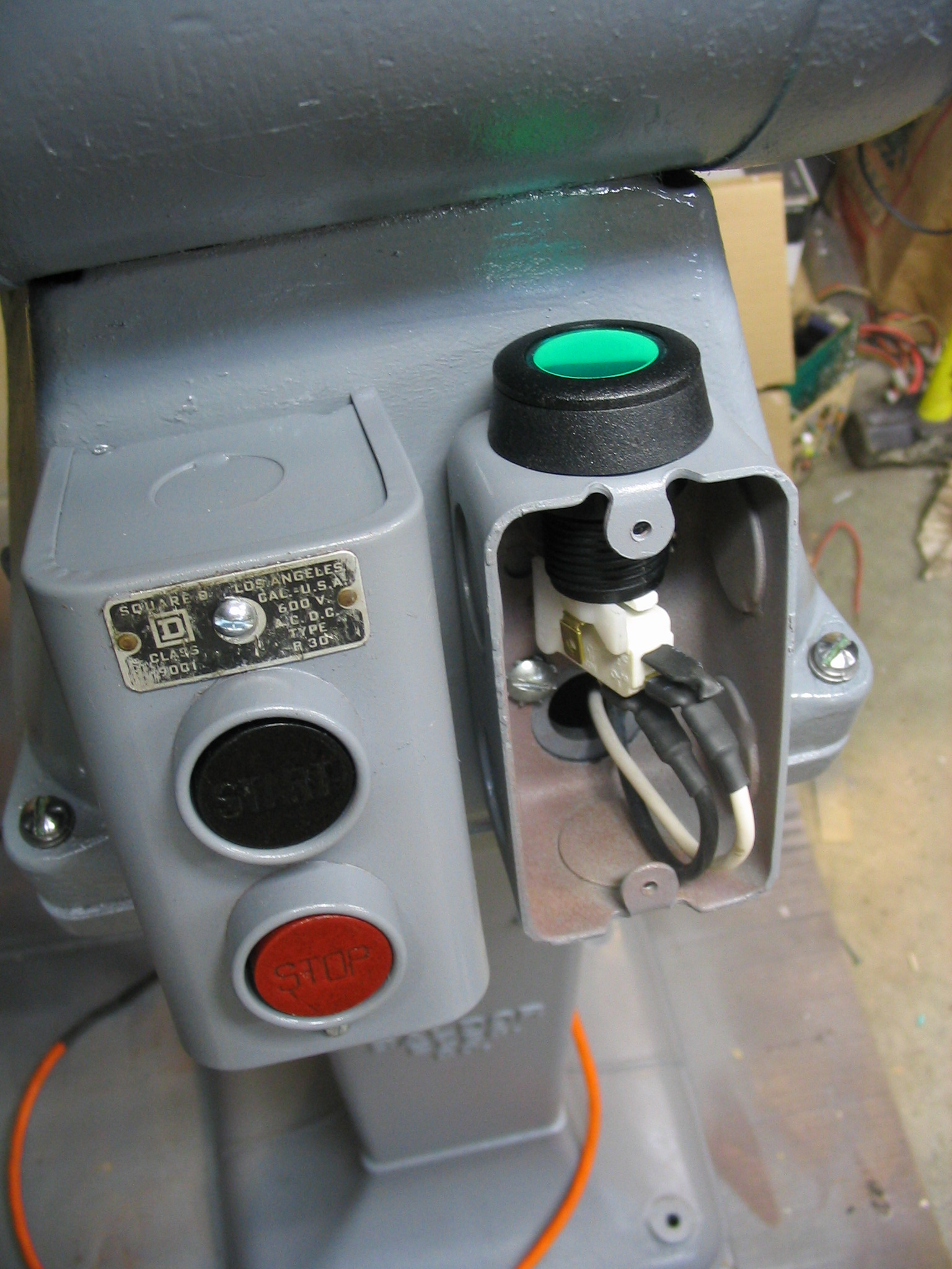
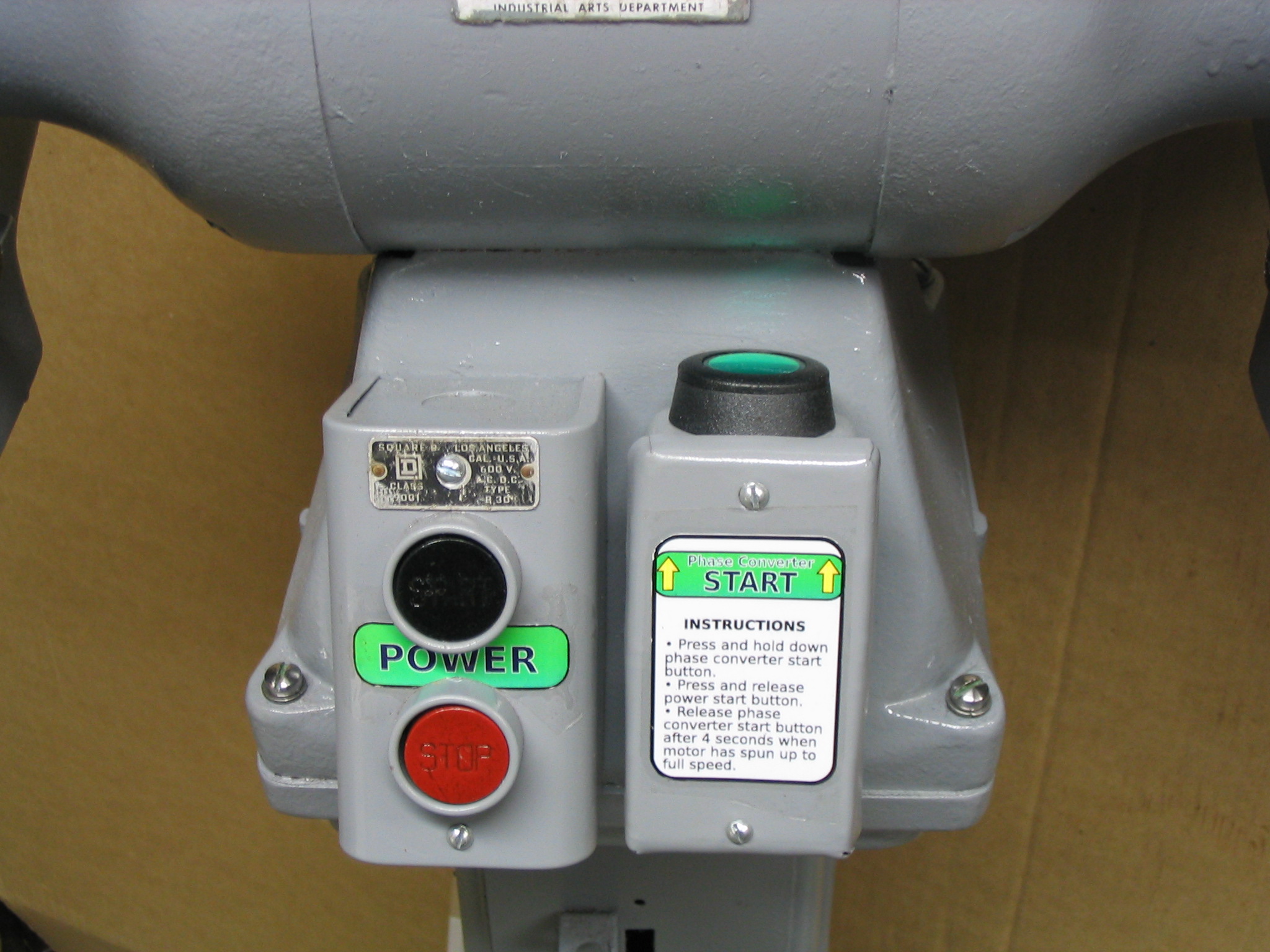
The phase converter needs an extra momentary push button to start the motor, so I added that to the front of the grinder next to the main on-off switch.
I received a Baldor metal grinder with 10-inch wheels, with a motor wired for three-phase industrial power. Three-phase power is not provided in U.S. residential homes, so I needed to power it from normal single-phase power. My solution was to build a balanced static phase converter, requiring only a few relatively inexpensive capacitors. (Much less expensive than the nuclear reactor I was considering.)
I knew I had some homework to do, to figure out how to make this work. I had ignored much information on 3-phase motors in the past, thinking that I would likely never need it. When would I ever come across any 3-phase equipment that would fit my miserly budget? Well, now, it seems.
The first resource I turned to was Electric Motors in the Home Workshop by Jim Cox, my favorite book on the subject. This book is written specifically to address reusing various industrial and appliance motors for home-built tools and uses, which fits my crazy schemes. It covered the basics of 3-phase motors, but did not go into great details. It did describe a very common method of generating 3-phase power from single phase, which is called a rotary phase converter. In this method, you use a single-phase motor to mechanically drive a 3-phase “idler motor” which generates the other 2 phases. This is a robust and flexible method which can handle multiple varying 3-phase loads. It also takes up some room, and requires two large electric motors dedicated to it. If you had a variety of 3-phase motors to run, it is a good solution. But it seemed like overkill for just my one grinder.
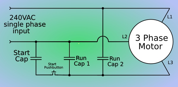
I did some more Internet searching, and came across another idea: the static phase converter. This is a very simple converter which uses capacitors matched to the amperage draw of the motor to generate the extra two phases. As long as your amperage draw does not vary much (meaning you can only really use it for one motor), this is a simple and inexpensive solution to the problem.
I found the best explanation and description in Rick Christopherson’s page on building a balanced static phase converter. I used his guidelines to determine the likely capacitor values I would need for my converter.
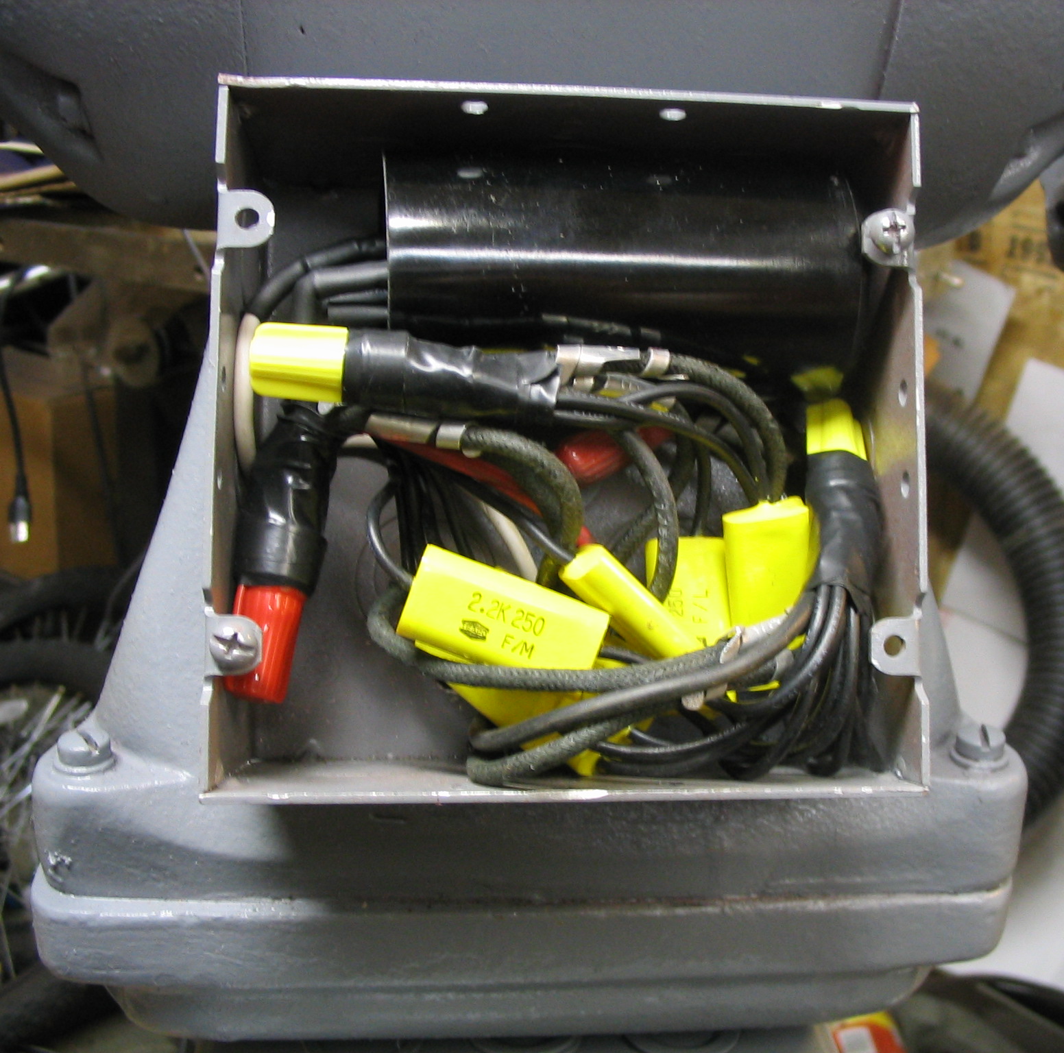
There are two run capacitors for the extra two phases. The two capacitors create pulses 120 and 240 degrees out of phase with the primary, so the second capacitor is twice the size of the first. Based on his tables, I guessed that my motor would require about 6 uF and 12 uF for the two phases.
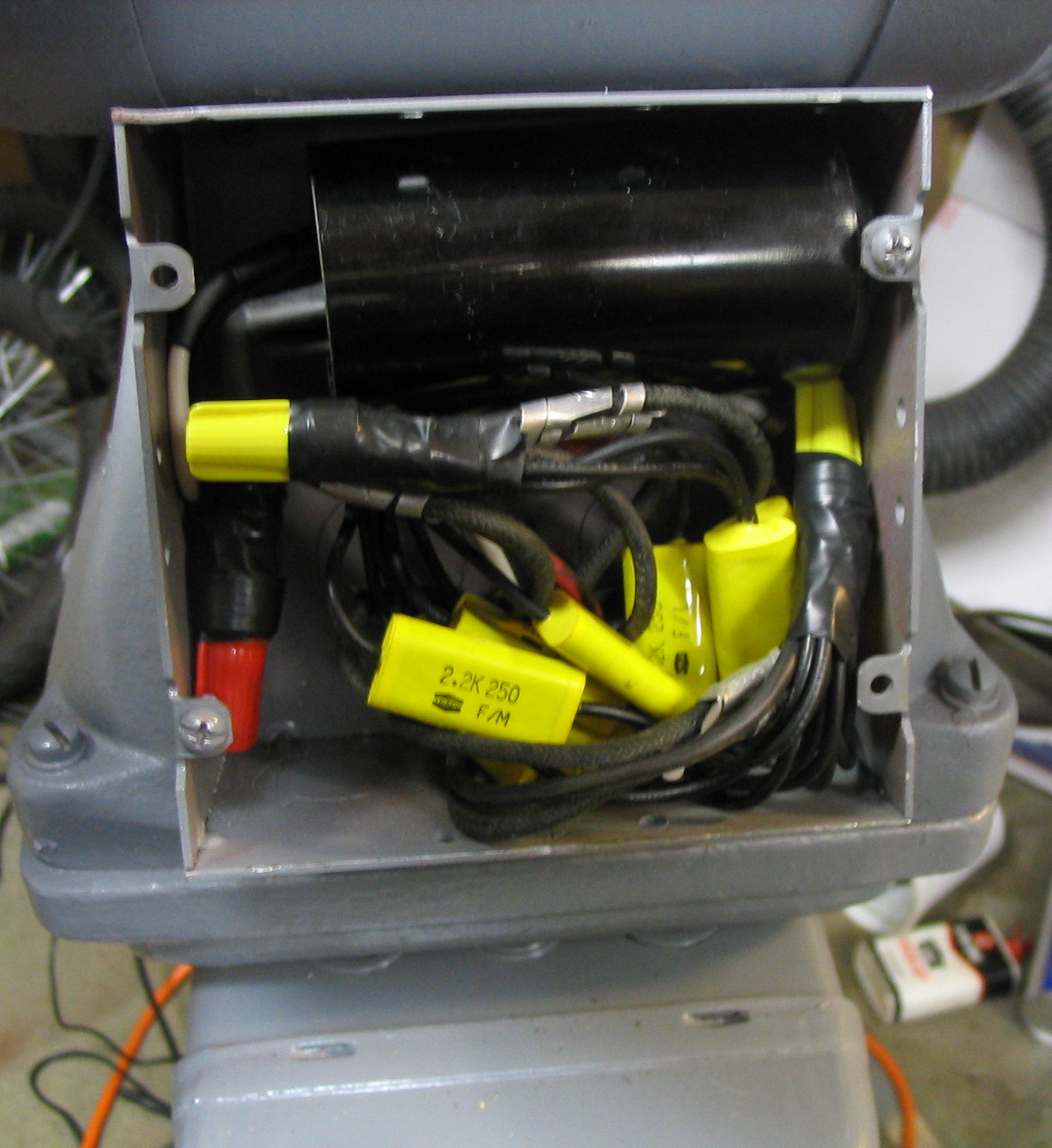
I went to a local surplus store, and was able to find smaller capacitors of 2.2 uF. My electricity textbook said that capacitors can be combined in parallel to add them up, so I just combined 3 for one phase and 6 for the other, providing 6.6 uF and 13.2 uF.
Just putting the run capacitors in the circuit would get it to run, but it would not start from a stand-still. With my dad helping me, we were able to spin the motor axle with a rope to get it started, and then turn on the power to make it continue running. It worked! I checked the power draw of all 3 phases with an inductive ammeter, and they were all nearly identical within 0.2 amps of each other.
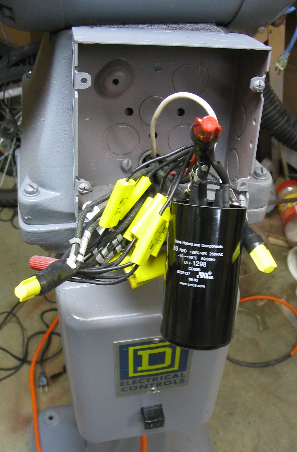
To bring the motor up to speed under power, it needs a large starting capacitor, connected in with a momentary push button. They are readily available, sold simply as A/C start capacitors. I had a capacitor from an old washing machine motor, which worked to start it as a test. I ordered another one of 86 uF from an Internet mail-order surplus place. Holding the start button for about 3 or 4 seconds is all that is needed to bring the motor up to full speed.
Construction
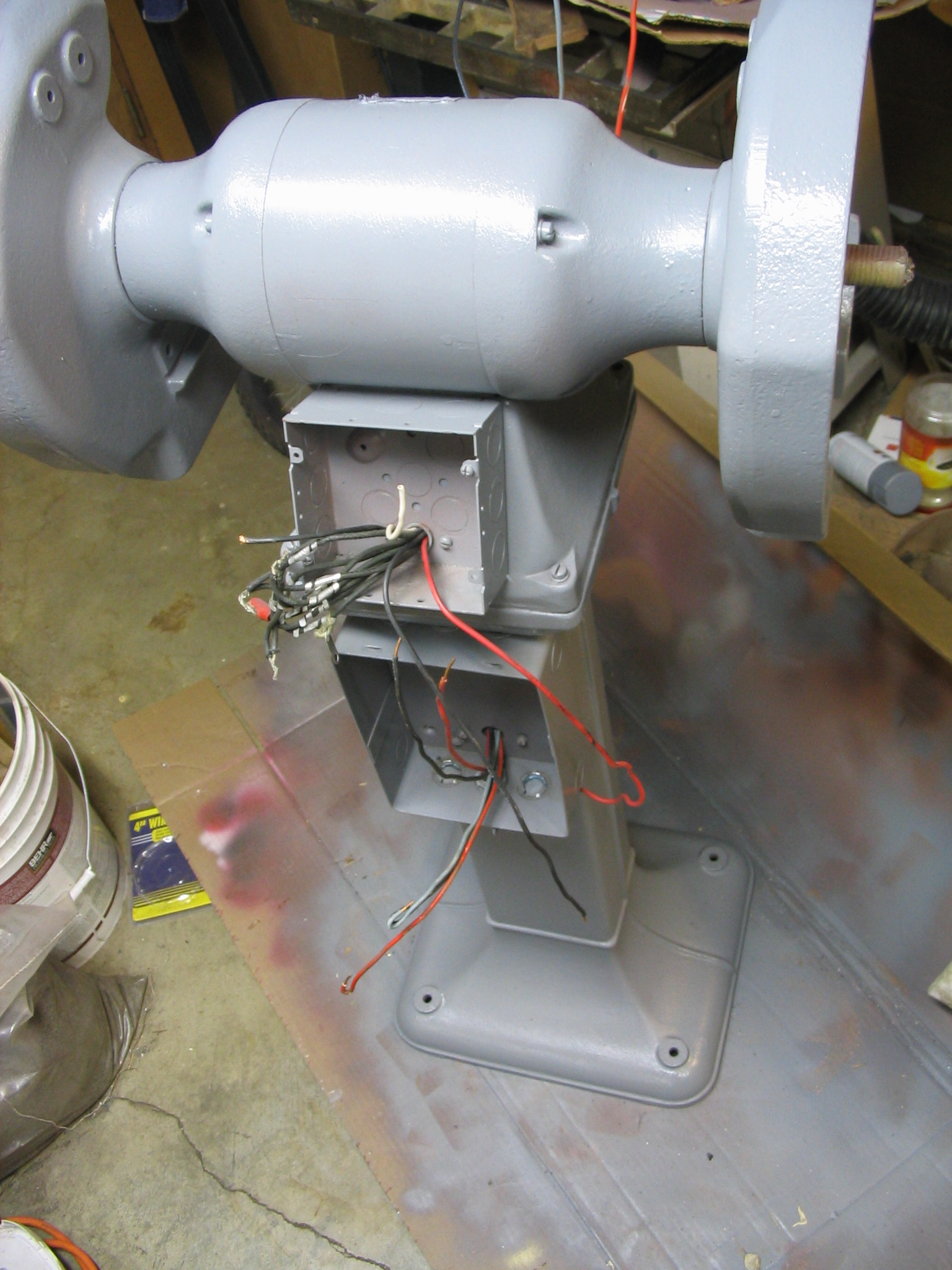
Figuring out the capacitor schematic and values was the hard part. The rest of the construction was relatively simple. The grinder already came with a large magnetic relay contact switch and circuit breaker, previously wall-mounted separately. I attached it to the back side of the pedestal stand, and put the push-button on/off switch on the front. I added two new electrical boxes: one on the front for the momentary start push button, and one on the back to hold the capacitors.
Since the voltage is double at 240v, I needed a different plug and outlet. But the amperage is low at 5 amps, so did not need a large super-heavy-duty power cord and plug like one might use with an electric clothes dryer or kitchen stove. I found a plug and outlet the same size as a standard US power plug, but with both prongs rotated at 90 degrees from standard, so neither side could be accidentally interchanged with a normal plug. Since the total amperage draw is only 5 amps, a 14-gauge power cord was adequate.
Result
I created some labels using Inkscape, printed them on photo paper, and attached them to the various boxes.
The end result was very satisfying. The motor only takes about 4 seconds to spin up to speed, and the grinder works great.
My new grinder needed some task lighting for the grinding wheels. I decided to build a dedicated lamp for each side, controlled by the grinder power switch. This worked in perfectly with my latest obsession, I mean interest, which is LED lighting.
Power
My first obstacle was the fact that the grinder runs of 240 volts, which is double the standard voltage in the US. My 20 amp power outlet and cord only provided the straight 240 volts; no neutral center tap was available to get 120v. For the LEDs, I needed a power supply which could accept 240v.
Fortunately, I had a couple of discarded laptop power supplies which would accept 240v, thanks to their international design. I used an HP Omnibook power supply which produces 19v DC output.
I bent some scrap sheet metal from an old VCR case into a small bracket that just fit the power supply, and painted the power supply and bracket both grey to match the grinder. I attached it to the back of the grinder in a convenient spot.
I ran the input power cord from the power supply down the side of the grinder stand, and attached it to the main power output terminals inside the relay box.
Laptop power supply
Mounted in bracket
Power cord
Power cord
LEDs
Light shade
LED array
Wiring
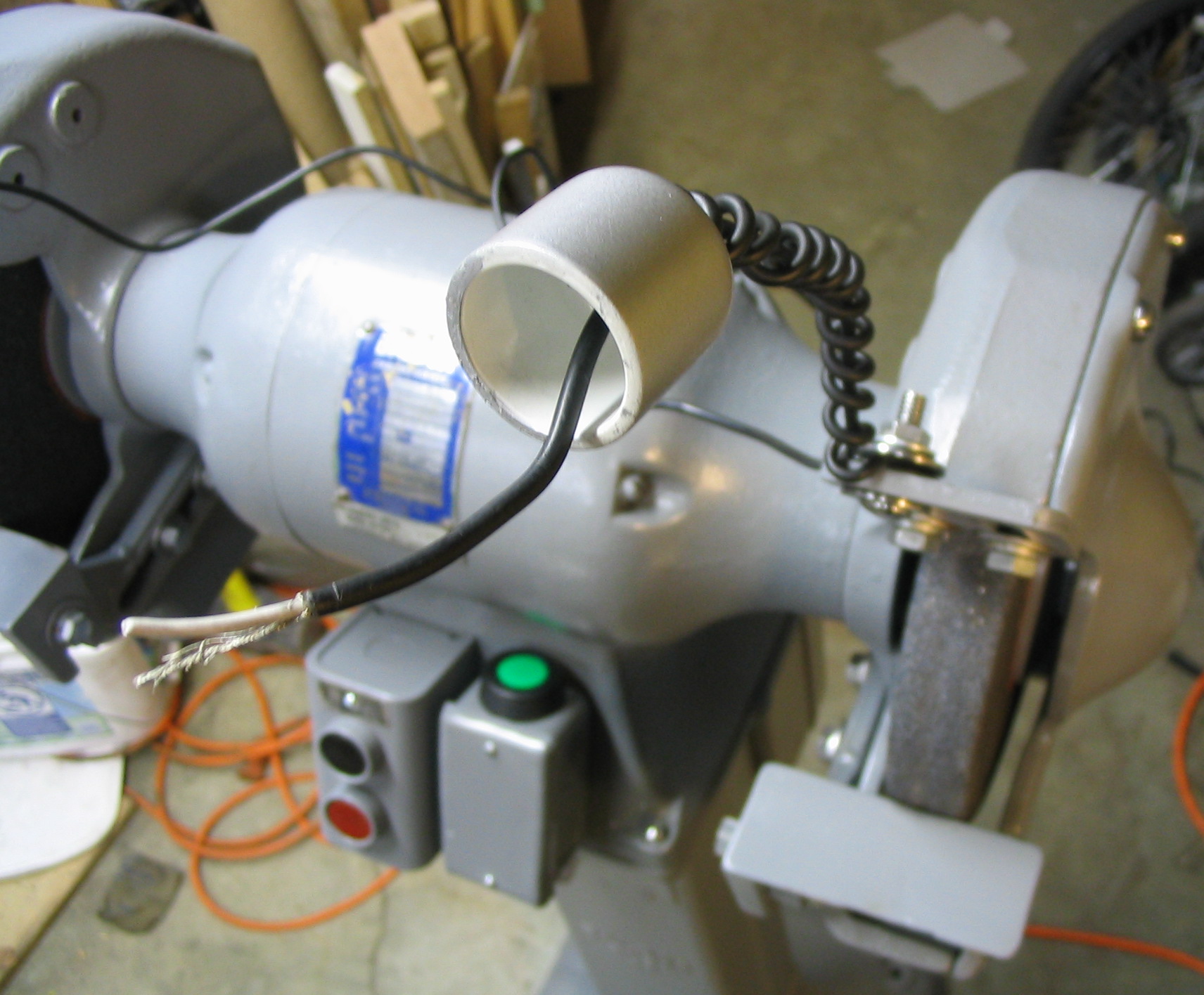
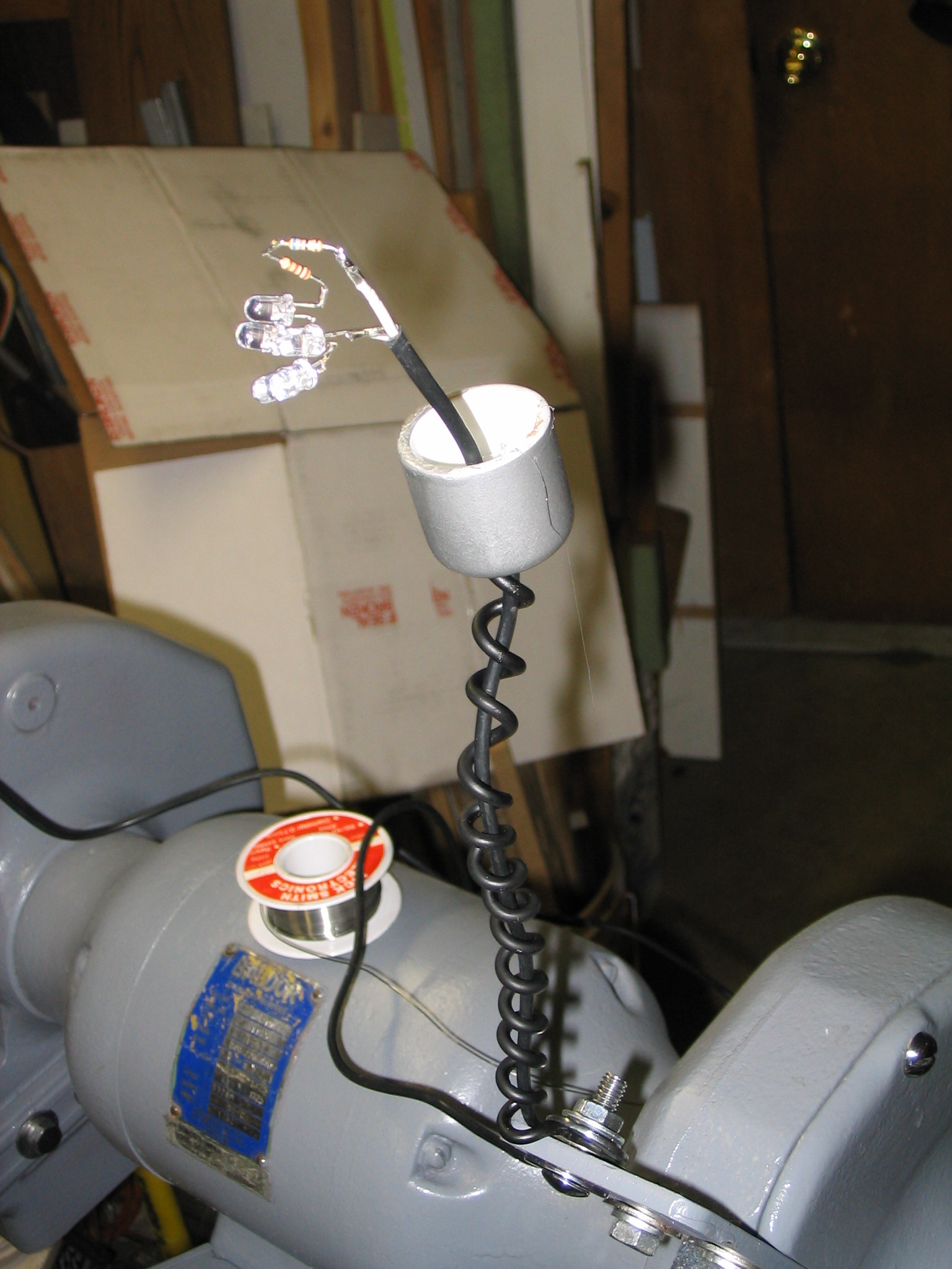
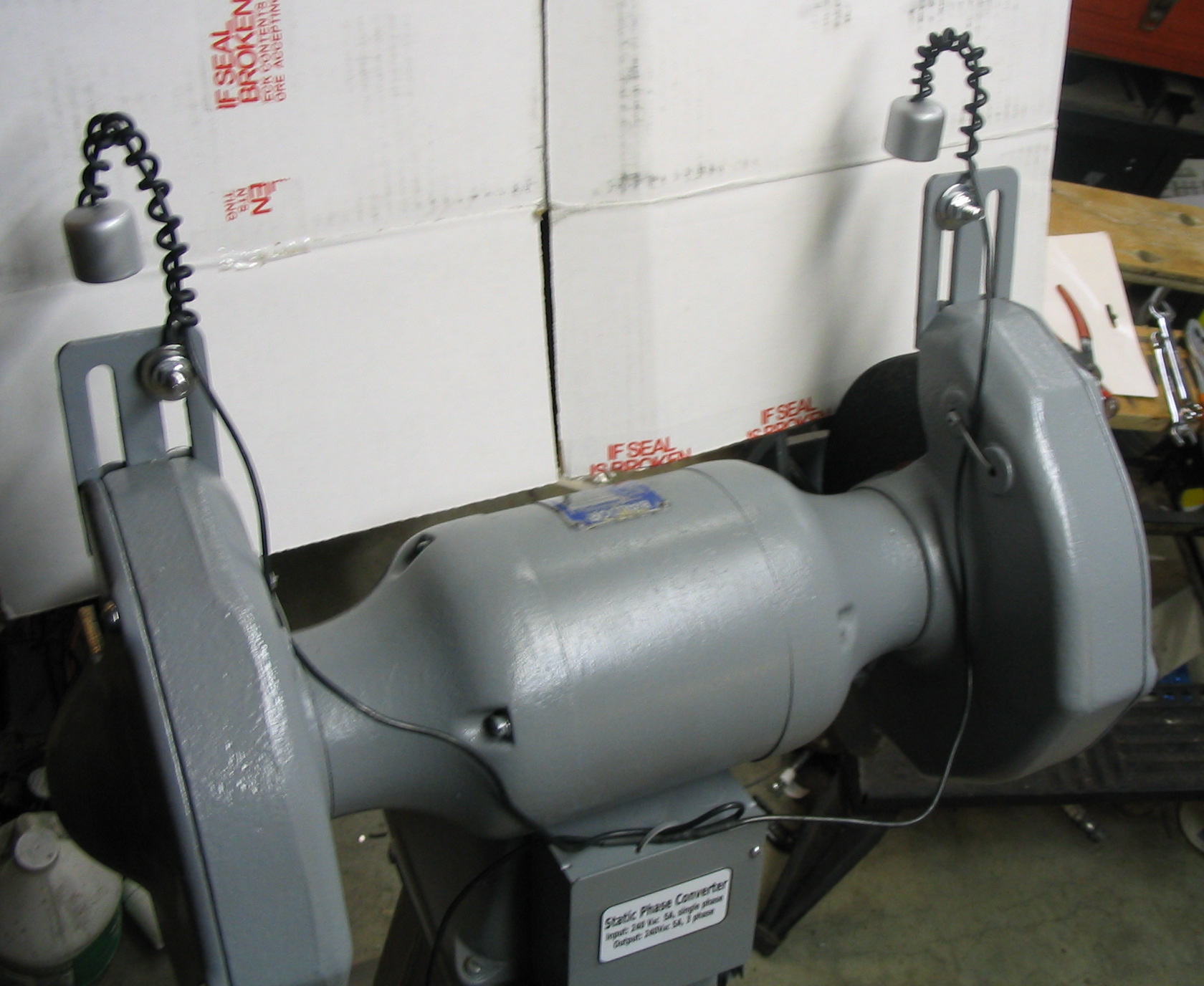
For the lamps, I made flexible necks by coiling solid copper wire around a rod. I left the insulation on the wire, and spray-painted it black using vinyl dye from the auto parts store. I ran the 19v output wire from the power supply up through the middle of the coil. The lamp shades at the end are PVC pipe caps from the hardware store, spray-painted silver.
Inside the PVC cap lamp shades are the LED arrays. Since white LEDs typically use around 3.3 to 3.5 volts, the 19 volts from power supply should be perfect to drive 5 LEDs in series, with a little left over for a current-limiting resistor. I measured the output of the power supply with my meter, and found that it actually produced 19.5 volts.
I used the LED resistor calculator to find that I would need a resistor of around 100 ohms in series with the LEDs. I wired up the 5 LEDs and the 100 ohm resistor in series, and tried it out with the power supply. They lit up nice and bright.
LEDs need to have the current limited externally, typically by a resistor as mentioned, and the average LED needs 20 milliamps. I measured the amperage in my circuit using my multimeter, and found that the actual current draw was 30 milliamps. While it might be fine, I decided to be a little more conservative and stick to the advised 20 milliamps.
The five LEDs were actually dropping 3.3 volts each, leaving 3 volts going through the resistor. 3 volts through the resistor at 100 ohms makes 30 milliamps. To reduce it to 20 milliamps, I changed the resistor to 150 ohms. Another check with the meter showed 20 milliamps as expected.
With that determined, I soldered the 5 LEDs and resistor to the ends of the 19v power wires sticking through the PVC cap. After wrapping the leads with electrical tape, I stuffed the LED array into the cap and pulled the slack out of the wire.
Results
I used a few zip ties to secure the wires, and with that, I was done. Starting the grinder turned on the lights. With the copper wire neck, I can bend it to point the light at whatever angle is best on the grinding wheel. It didn’t take too long, and produces a decent light. I might just have to do this to all my tools.
Many people have light-up Christmas decorations in their yard. A popular one is the white-wire reindeer, covered with mini lights. Having another yard with another reindeer sounded boring. What really sounded good would be to have what almost nobody else has: a moose.
I bought a reindeer from the store and overhauled it. I studied pictures of moose, and got an idea of how their heads and shoulders varied from deer. And, of course, the antlers. I sketched the new shape in full size on paper, tracing around the existing wire deer head.
I got some heavy-gauge steel wire from the hardware store, and bent it to match my drawing. I scraped off the white paint from the deer head where the wires met, and soldered it together with a propane torch. Then I painted it with white spray paint.
Since the head and antlers were bigger than before, it needed more mini lights. I got more lights and redid the shoulders, head and antlers. The result: a one-of-a-kind Christmas moose. Merry Chrismoose!
I have an old laser printer which does not have a decent standby power-saving mode. I built a computer-controlled power switch for it, so the computer turns on the printer when there is a print job, then turns it off again later.
The printer is not near to the family computer, but in an out-of-the-way place in the basement. Because it doesn’t have a power-saver mode, it has been on a mechanical timer switch. Turn the knob, and the printer will stay on for 45 minutes. We had to go down and turn on the printer, go back up to the computer and print, then go down and get the printout from the printer. Good exercise, but annoying.
Existing solutions
I could have used off-the-shelf units from the X10 control system. This home automation system has been around for years and is well known and reliable. Since I don’t know much about electronics and have not built a computer-controlled real-world interface before, this would have been a good simple solution to the problem. But I have more fun breaking, I mean making things myself, so I built my own solution. Other people have done similar things, and I’m learning from their examples.
Design parameters
My laser printer is an Apple LaserWriter Pro 630. Its label says it can pull up to 5 amps of current. This would represent the highest load possible, most likely at power-on when the fuser is warming up. I want my switch to accommodate this plus some safety margin, so I’m using 7 amps as a minimum figure to be extra safe.
I send print jobs to the printer from my Linux server, using the CUPS print spooler system and the NetAtalk software. It sends the print jobs over Ethernet to the LaserWriter using the AppleTalk PAP protocol.
The software needs to turn on the power switch, wait until the printer is ready to respond, send the print job, and then turn off the power switch afterwards.
Serial port
There are many ways that a computer can interface to the outside world. Two common and popular choices on PC hardware are the RS232 serial port (“COM”) and the Centronics parallel port (“LPT”). I selected the serial port, since my server has two available and I’m not using them for anything else.
In reading up on serial ports, people caution that you should not try to draw too much current from the serial port or you could burn it out. A number of references said that you should not draw more than about 5 milliamps. This is a very small amount of electricity, and is not going to be enough to drive a good-size relay big enough to switch 7 amps. Therefore I will need something in between the RS232 signal and the 7A relay coil.
Electrically, the RS232 signal is interesting. The voltage can vary anywhere from around 4V to 20V. A binary one is a positive voltage, and a binary zero is a negative voltage.
If I knew more about electronics, I’d cook up a circuit with a voltage regulator and transistor and some other neat gizmos to drive a big relay. But I took the easy way out and just selected a solid-state relay in series with a diode. The diode makes sure the RS232 negative voltage for the binary zero is filtered out, so only a binary one will activate the solid-state relay. The SSR takes very little current, and operates from 3V to 24V input, which matches RS232 nicely. I bought the SSR from the local electronics store, and I pulled the diode out of a broken radio.
Solid state and mechanical relays
The solid-state relay, in turn, activates the mechanical relay with the high-current contacts. I used an SSR with 120VAC output, and a mechanical relay with a 120VAC coil, so I didn’t need any power source other than the RS232 signal and the 120VAC line power.
Software
To drive the switch, I need to turn on the DTR signal of the serial port when the printer should turn on, and turn off the DTR pin when the printer should turn off. I decided to activate the printer at the start of a print job, and deactivate it after a fixed period of time (30 minutes by default), if no new print jobs have shown up.
I found that the Linux serial port device drivers will control the DTR signal according to their own whims when a program opens or closes the port. Therefore I need a constantly-running background daemon to open the port, and then toggle the DTR signal as needed.
There are many ways to communicate with a background daemon. I chose the simple approach of a control file. When the file is created, the daemon turns on DTR. When the file is deleted, or the timestamp of the file is too old, the daemon turns off DTR. So when a print job needs to turn on the printer, a simple “touch” of the control file will turn it on.
Construction
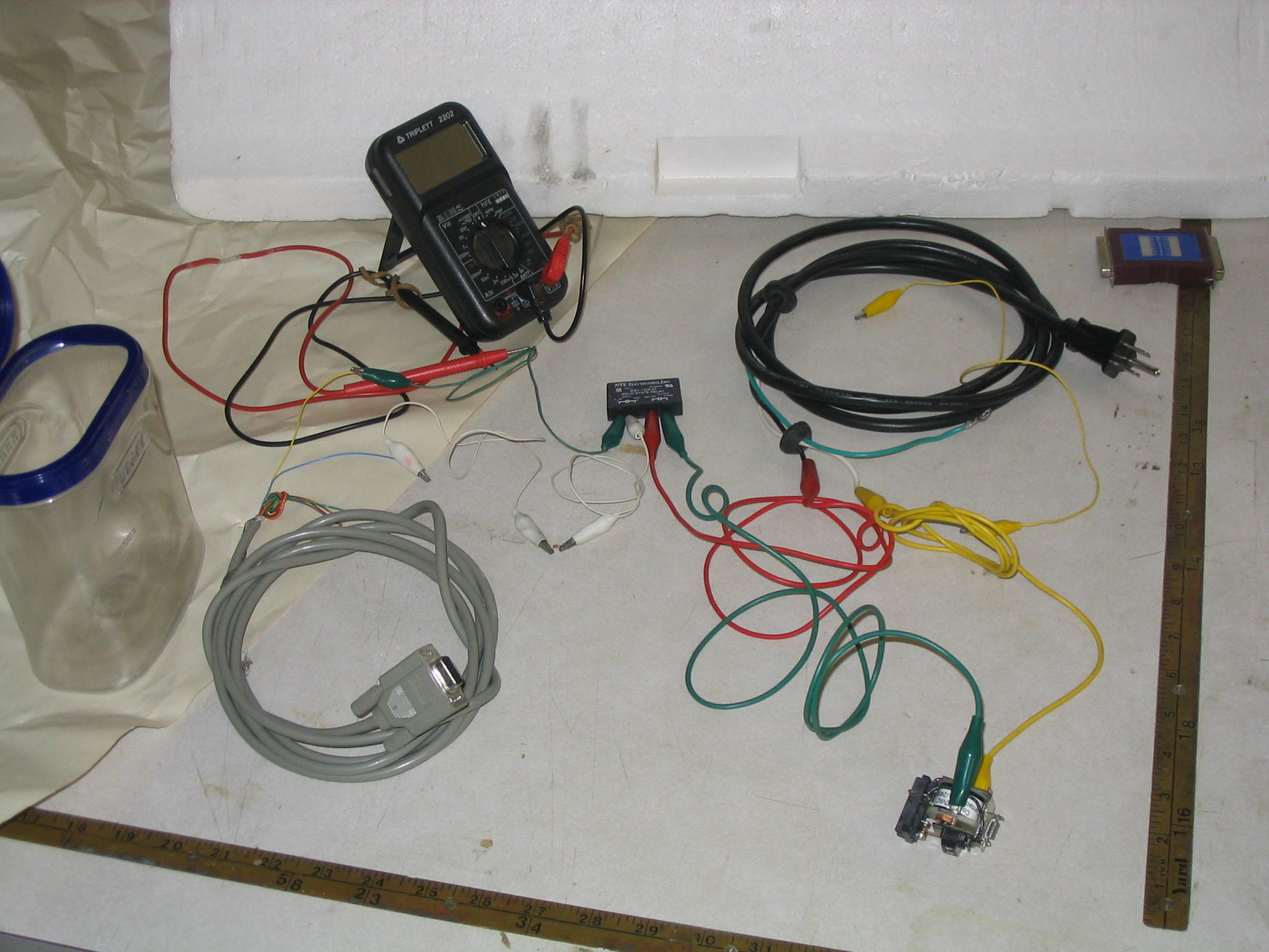
Assembling the parts to test
With the software working, I assembled the hardware. I first connected the components together with alligator clips to make sure it worked. The big relay clicked on and off to match the DTR signal, as I had hoped.
I used a clear plastic mayonaise jar as a case, and cut holes in the lid for the power outlet and master switch. The two-pole master switch allows the power output to be always off, always on, or controlled by the relay.
Silicone sealer
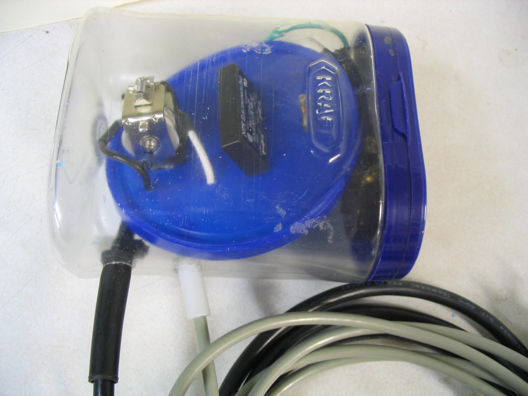
To keep things neat, I mounted the two relays and the diode on a piece of plastic (actually a lid from a can). I was short on shrink-wrap tubing, so I covered the exposed wire connections with clear silicone sealer to prevent shorts.
I tested it one more time, and made a strange discovery. The power output was stuck on, regardless of the state of the DTR line. Somehow my circuit was shorted out. I double-checked my connections, and could not find any wires out of place. Then I found the culprit: I had not used silicone sealer. I had used clear latex caulk. Latex caulking is water-based, and water conducts electricity. Even after drying for more than a day, it still was conducting electricity and shorting my circuit. I scraped off all of the latex caulk, and then it worked.
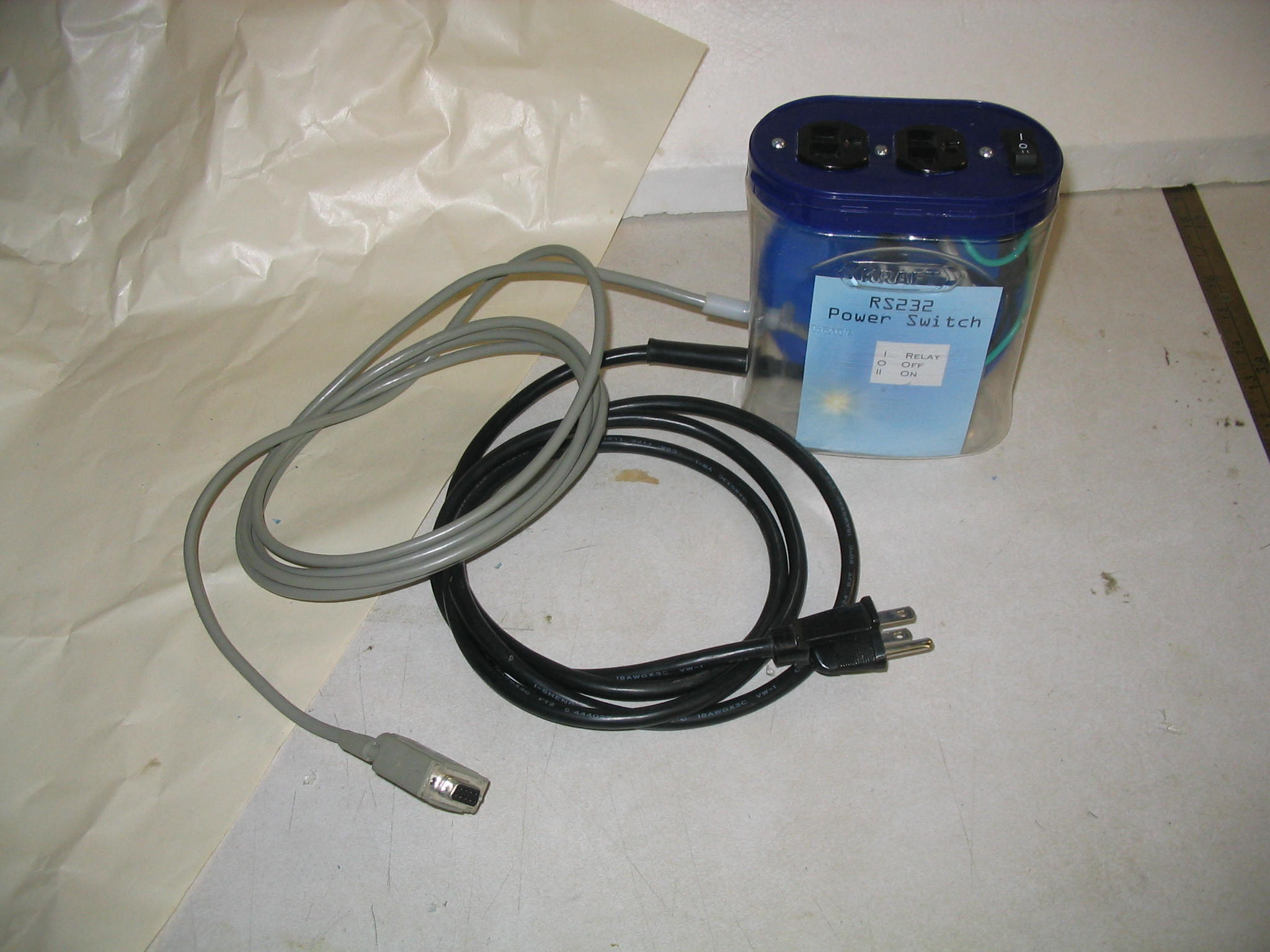
End result
Completed switch
The end result was a nice power switch that works as well as I had hoped. My daughter the artist helped me make a fancy label using the GIMP, which we printed on photo paper and stuck inside. Success!
Code listing
Here is the Perl code for the background daemon which monitors the control file and sets the DTR line to match.
port-handler.pl
#!/usr/bin/perl -w
# Serial port line control
# Control a relay hooked to the serial port using DTR line. # Run as a daemon.# Monitor file for control action# – If file created recently, turn on line.# – If file deleted or too old, turn off line.
#——————————————–# Modules/directivesuse strict;use Device::SerialPort qw( :PARAM :STAT 0.07 );use Getopt::Long;
#————————————–
my $CheckTimeSeconds=10; # seconds between file checksmy $ControlFileName=”/var/run/port-dtr”; # file to monitormy $TimeoutMinutes=45; # turn off after this much time- 30 minutesmy $SerialPort=”/dev/ttyS0″;my $debug=0;
my ( $result, @filestat, $filetime, # last mod timestamp of control file );
$result=GetOptions ( “checktimeseconds=i” => $CheckTimeSeconds, “timeoutminutes=i” => $TimeoutMinutes, “portname=i” => $SerialPort, “debug=i” => $debug, “controlfile=i” => $ControlFileName );
# Open portDebugMsg ( “Starting with:n”, ” checktimeseconds=$CheckTimeSecondsn”, ” timeoutminutes =$TimeoutMinutesn”, ” portname =$SerialPortn”, ” controlfile =$ControlFileNamen”);
DebugMsg ( “Open portn”);
my $PortObj = Device::SerialPort->new($SerialPort) or die “Error: cannot open serial port: $! n”; ;
# Turn off status$result=$PortObj->dtr_active(0);
while (1) {
if ( -f $ControlFileName ) { @filestat = stat $ControlFileName; $filetime = $filestat[9]; if ( ( time – $filetime) > ( $TimeoutMinutes * 60 ) ) { # file expired; turn off DebugMsg ( “File expired; Turn off dtrn”); $result=$PortObj->dtr_active(0); } else { # file is recent; turn on DebugMsg ( “File is recent; Turn on dtrn”); $result=$PortObj->dtr_active(1); } # if time } else { DebugMsg ( “File is gone; Turn off dtrn”); $result=$PortObj->dtr_active(0); } # if controlfile exists
sleep $CheckTimeSeconds;
} # while
#—————————–sub DebugMsg { my @Message =@_;
if ( $debug ) { print STDERR “@Messagen”; } } # sub DebugMsg
/usr/lib/cups/backend/pap
added just before the pap command is run:
# Turn on power switchtouch /var/run/port-dtr# See if printer is therePrinterFound=` $nbplkup $nbpname | wc -l `while [ $PrinterFound -eq 0 ] ; do sleep 20 PrinterFound=` $nbplkup $nbpname | wc -l ` sleep 10done
When working with electricity, it is important to ensure you have electrical wires large enough to carry the load. The diameter of the wire is referred to as the wire gauge. A smaller number is a larger wire.
If your wires are too small for the current, they can overheat and start a fire. Of course, for any questions, consult a licensed electrician.
Wire size requirements are based on amperage, not voltage. There are tables available to tell you what wire gauge you need for a given amperage.
Two common sizes in household electrical wiring: 14 gauge wire can carry 15 amps safely, and 12 gauge wire can carry 20 amps.
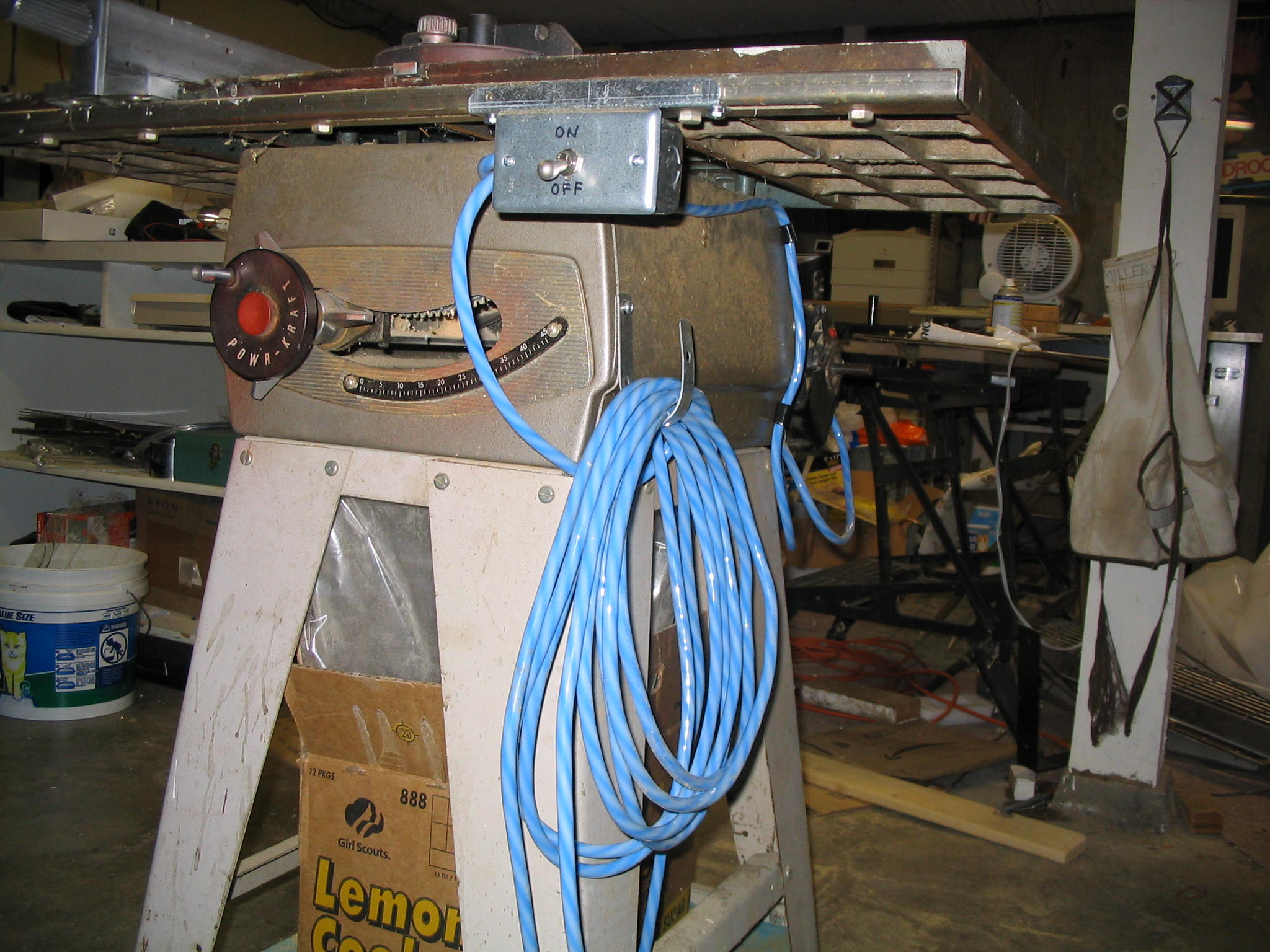
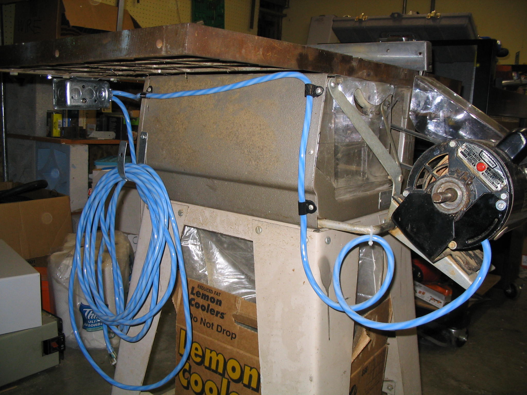
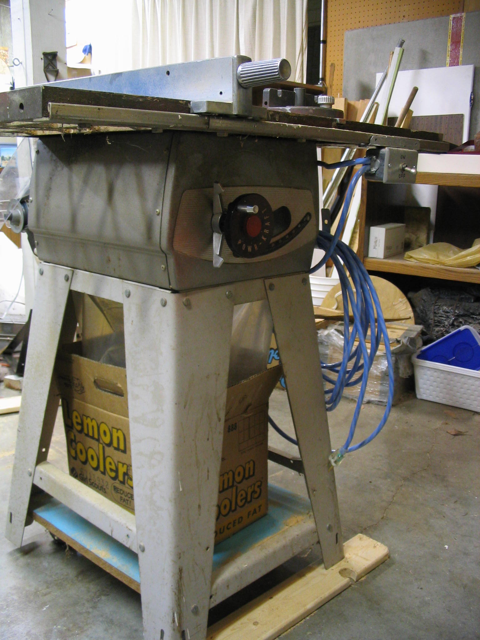
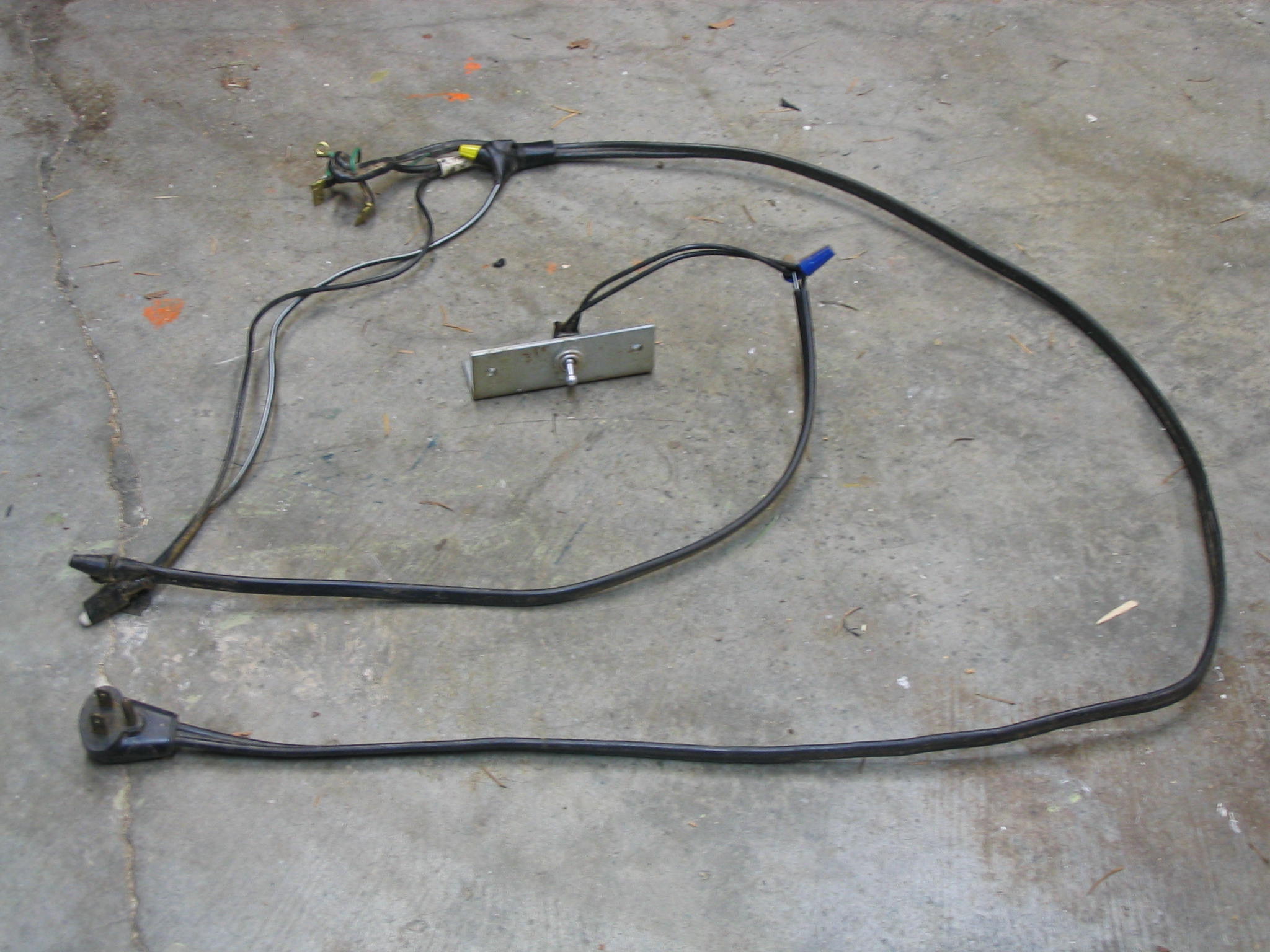
My used tablesaw needed a new power cord and switch. The cord was clearly in bad shape. The on-off switch was spliced in with a mess of wire nuts and electrical tape. It was time for some basic electrical repair.
The label on the motor said it would pull up to 14 amps at full load. I replaced the cord completely using a 14-gauge extension cord I got on Christmas clearance sale at Home Depot, which is rated to carry 15 amps. I added a safety switch, which must be pulled out and forward to turn it on, and mounted the switch in a proper electrical box with no exposed terminals or wires.
There are a number of considerations when replacing a switch and cord on an appliance or power tool.
Maintain proper grounding. The motor already had a ground lug for the cord, which I connected securely. I also attached the ground wire to the new metal switch box I installed, thereby ensuring a good ground for the table saw frame as well.
Use the correct wire size. 14 gauge should carry up to 15 amps safely.
Switch the “hot” wire. In household AC wiring, there is a black “hot” wire and a white “neutral” wire. Although both carry electricity, the hot wire should always be switched instead of the neutral. This is important in case of a short circuit, to maintain safety.

 I received a Baldor metal grinder with 10-inch wheels, with a motor wired for three-phase industrial power. Three-phase power is not provided in U.S. residential homes, so I needed to power it from normal single-phase power. My solution was to build a balanced static phase converter, requiring only a few relatively inexpensive capacitors. (Much less expensive than the nuclear reactor I was considering.)
 I did some more Internet searching, and came across another idea: the static phase converter. This is a very simple converter which uses capacitors matched to the amperage draw of the motor to generate the extra two phases. As long as your amperage draw does not vary much (meaning you can only really use it for one motor), this is a simple and inexpensive solution to the problem.
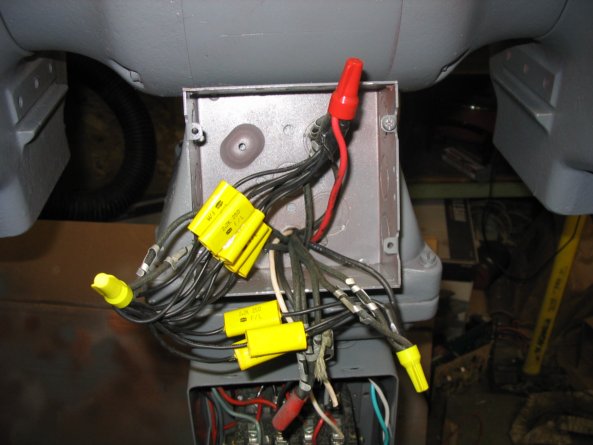
 To bring the motor up to speed under power, it needs a large starting capacitor, connected in with a momentary push button. They are readily available, sold simply as A/C start capacitors. I had a capacitor from an old washing machine motor, which worked to start it as a test. I ordered another one of 86 uF from an Internet mail-order surplus place. Holding the start button for about 3 or 4 seconds is all that is needed to bring the motor up to full speed.
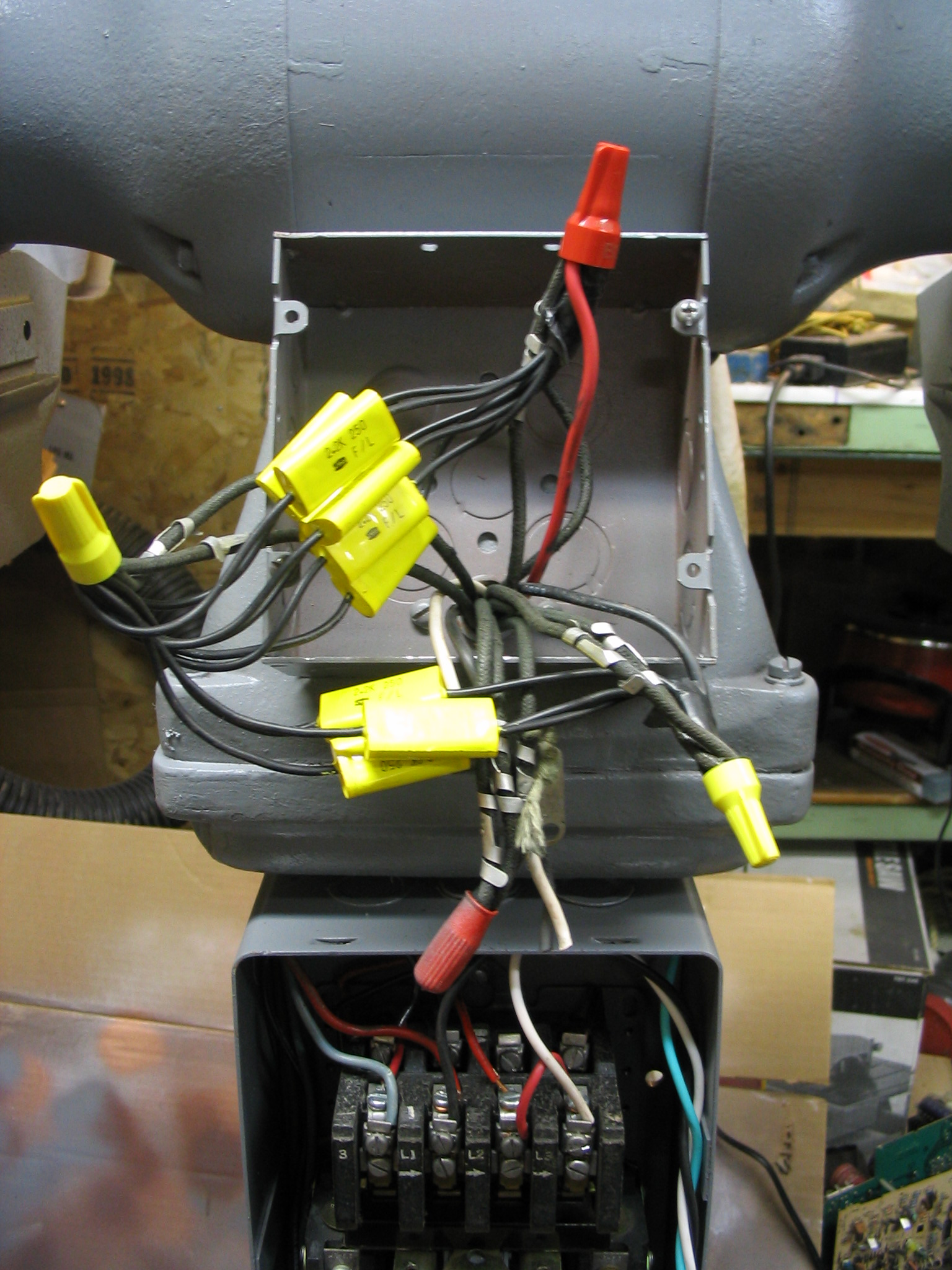
 I created some labels using
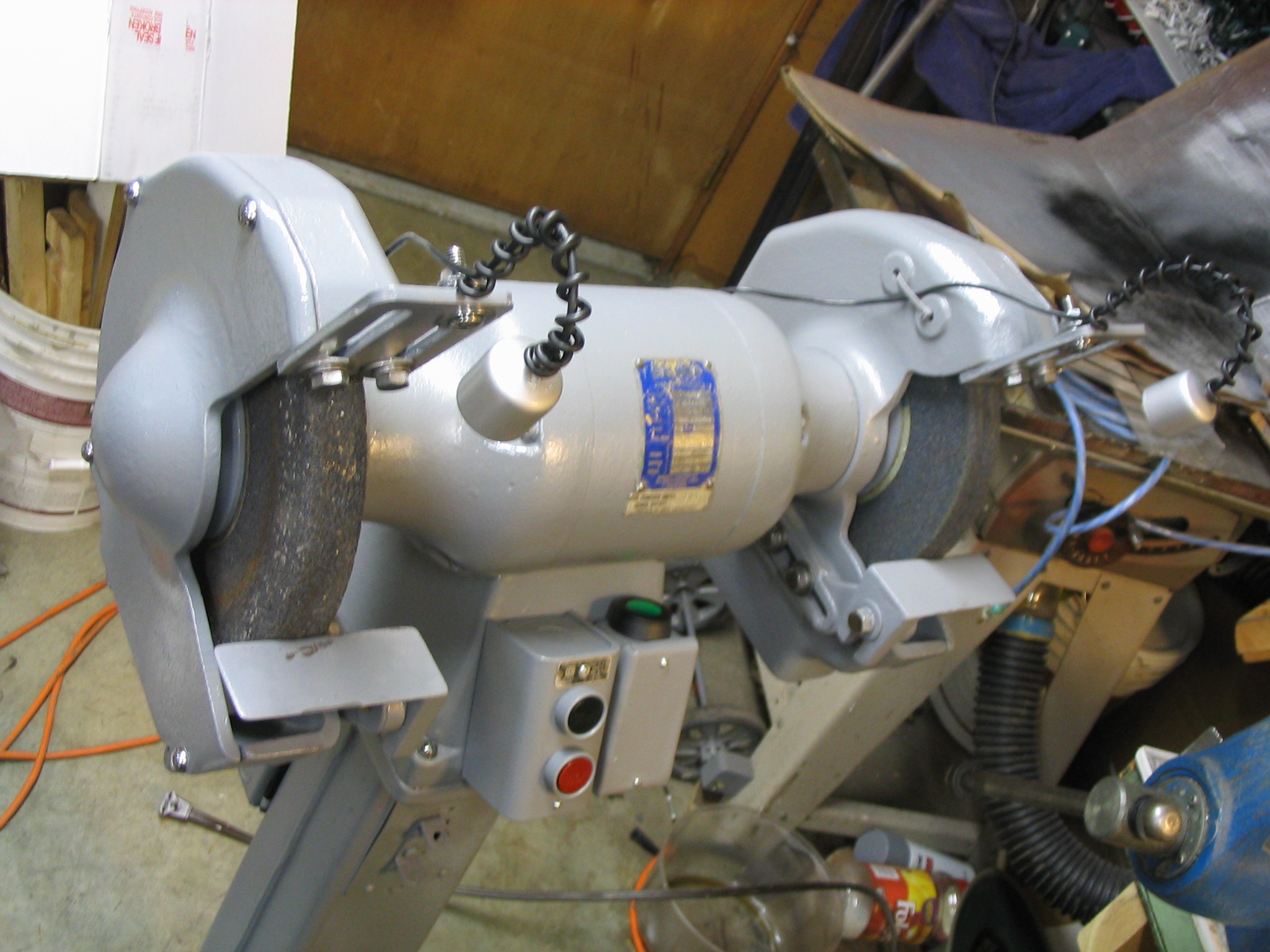


 Many people have light-up Christmas decorations in their yard. A popular one is the white-wire reindeer, covered with mini lights. Having another yard with another reindeer sounded boring. What really sounded good would be to have what almost nobody else has: a moose.
 I bought a reindeer from the store and overhauled it. I studied pictures of moose, and got an idea of how their heads and shoulders varied from deer. And, of course, the antlers. I sketched the new shape in full size on paper, tracing around the existing wire deer head.
 Since the head and antlers were bigger than before, it needed more mini lights. I got more lights and redid the shoulders, head and antlers. The result: a one-of-a-kind Christmas moose. Merry Chrismoose!
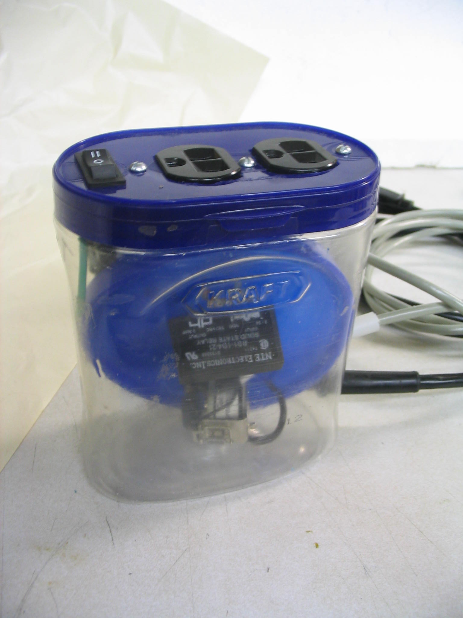

 My used tablesaw needed a new power cord and switch. The cord was clearly in bad shape. The on-off switch was spliced in with a mess of wire nuts and electrical tape. It was time for some basic electrical repair.