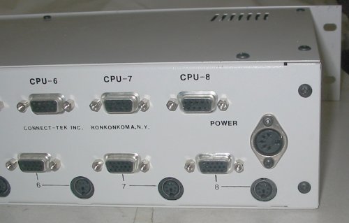
 I acquired an older Connect-Tek KVM (PC keyboard/video/mouse) switch. I got it for free because it was missing the power supply. I decided to make one.
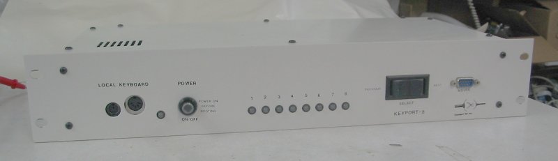
I sent an email to the company and received a very helpful reply about the specifications of the power supply.
The Complete Idiot’s Guide to Electrical Repair Amazon IndieBound |
Following are the specification of the power supply it used: Output: 12V AC center tap, 1.2 amp Pinout of 5 pin din: the 2 extreme outside pins are VAC Center pin is center tap Shell is grounded. It may be available from: Condor Electronics, 408-745-7141 Part# WP573512CG-5DIN: verify the specifications before you order.
I decided for fun to build my own power supply to these specifications. This is not a project that one would undertake to save time or money. Rather, this is a project to do simply for the enjoyment of creating something and seeing it work and be useful.
Safety: Working with electricity can be dangerous. The 120V electrical input is hazardous, and can possibly injure or kill you. If you don’t know what you are doing, ask an expert and learn about it. Observe and follow all proper safety precautions.
Looking at the specs, this is a very simple power supply. The input and output are both alternating current, so it only requires a simple transformer, and no electronics to convert AC to DC. The only term I was not familiar with was “center tap”. This means that there are 3 output wires: two “outer” and one “center”. Between the two outer wires it is 12 volts, but from either outer wire to the center it is 6 volts. (This works the same as U.S. 240V split-phase household electrical wiring.)
How to Test Almost Anything Electronic Amazon IndieBound |
The current rating of 1.2 amps is somewhat large compared to your average little power adapter. It is important that your wire is large enough to carry the current without overheating. Wire size is a function of amperage, regardless of voltage. I consulted a wire gauge chart to find the minimum wire size required to carry 1.2 amps. Looks like I need at least 21 gauge wire (smaller gauge number is larger wire). I had some 24 gauge wire and 18 gauge, so I used the 18.
The power connector on the box is called a 5-pin DIN connector. It is the same connector used on the older, larger AT-style PC keyboard connector. Since I had a dead keyboard in my junk pile, I decided to reuse the connector from it for this. When I compared the wires in the keyboard cable with other wire I had, I decided they were too small for the amperage required. I cut off the cover from the connector with a hack saw, and soldered on the 18 gauge wire. Then I covered it with silicone sealer, which you can get from your local hardware or home-improvement store. I wrapped it around with masking tape while the silicone dried overnight. 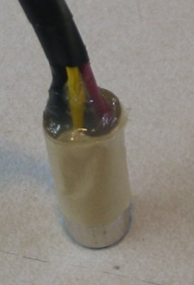
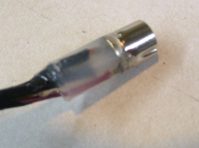
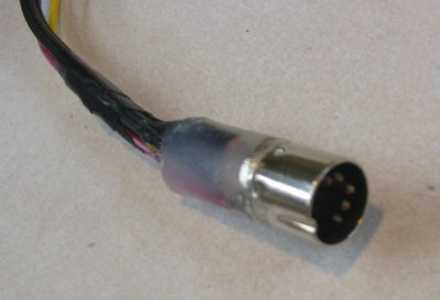
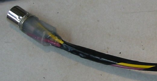
Then when it dried, I removed the masking tape, leaving an insulated but flexible connection.
I ordered a 12V center-tap transformer from All-Electronics, part number TX-122. Then I tested it to see if it worked. 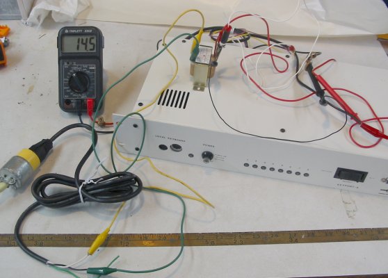
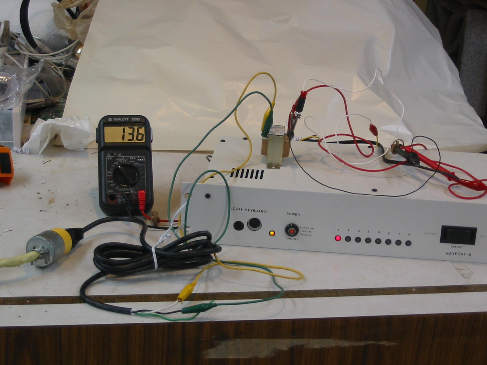
Fortunately, it worked! You can see in the pictures that the power supply said it produced 14 volts with no load, when the KVM was off. It then dropped to 13 volts when the KVM was powered on. This is normal.
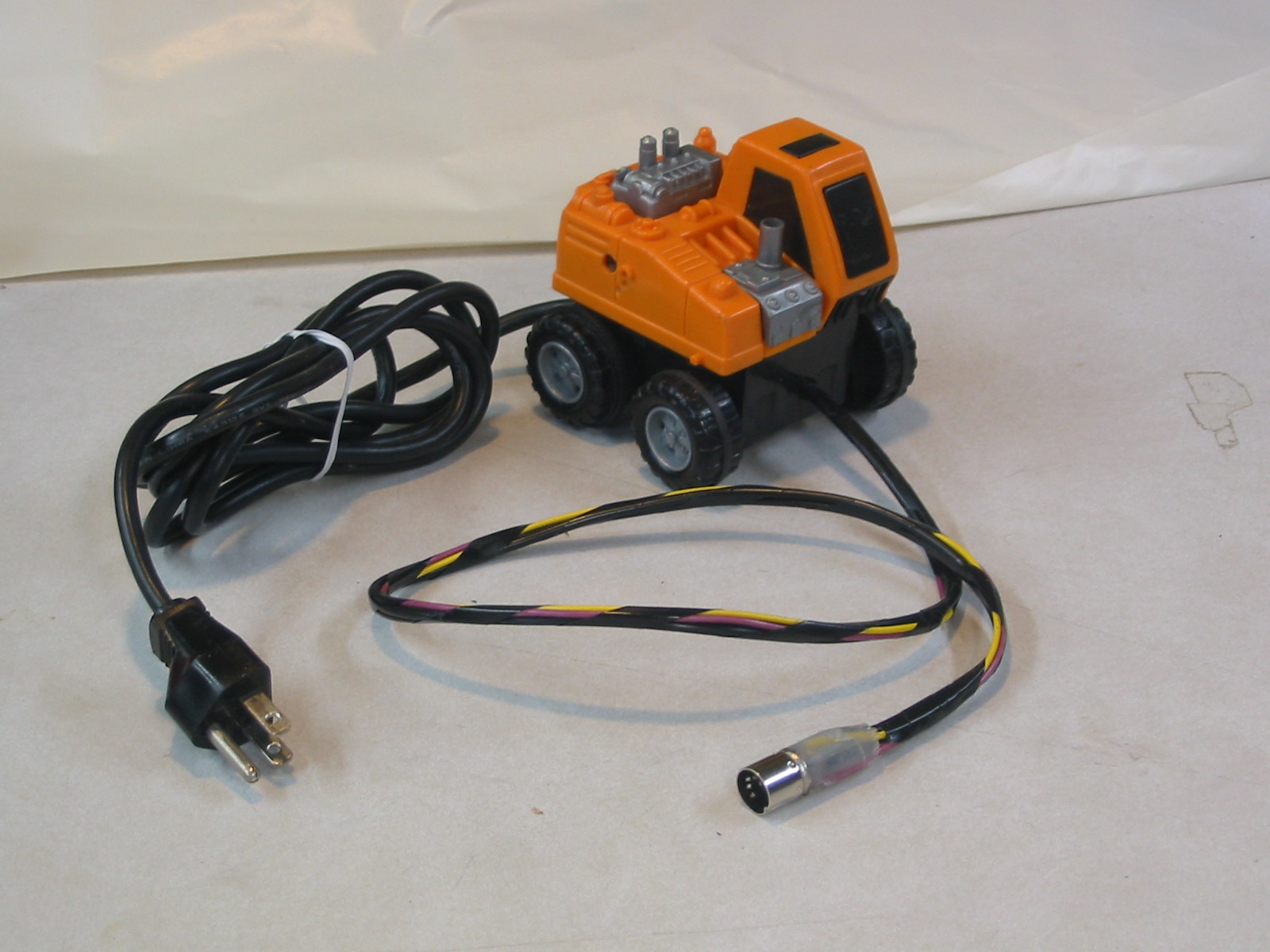
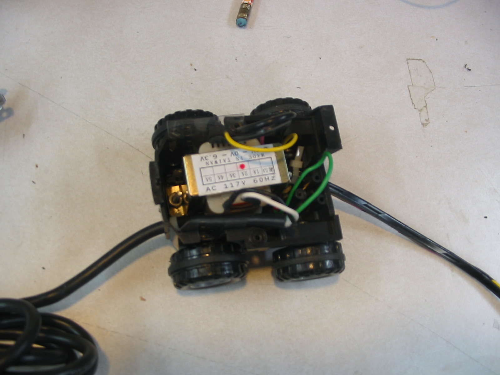
It is important to encase the transformer in a box for safety reasons. You can’t leave the electrical wires out and exposed because the 120V input is hazardous, and if any metal shorted out the pins you could damage your equipment. A small plastic box is ideal. I found a small plastic truck of about the right size and shape, so I decided it was the perfect case for my transformer. 
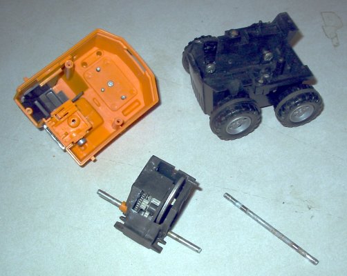
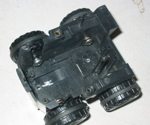
It contained a small friction motor, the kind where you push it forward along a surface to wind up the flywheel and then let go. I removed the friction motor and the other axle. I then used screws to hold the wheels to the base, leaving room for the transformer in the middle. I drilled a 1/4-inch hole in each end for the wires, and soldered them to the transformer. Note the ground wires: since the power supply specification said the DIN shield is grounded, it will be connected with the transformer mount to the 120V ground. 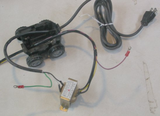
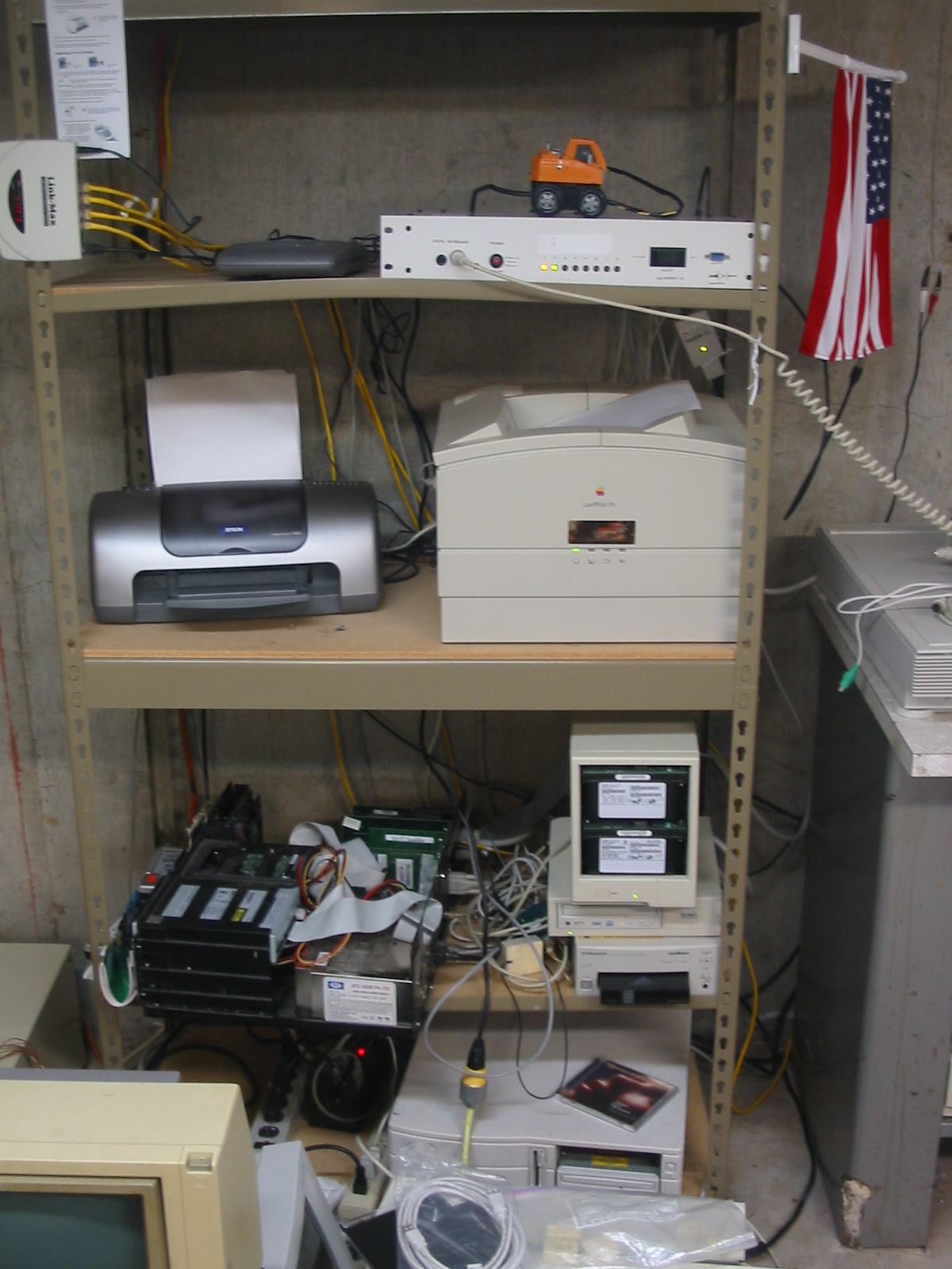
Once it was done, I put the KVM and power supply on the shelf with my computer equipment. The project was a success. 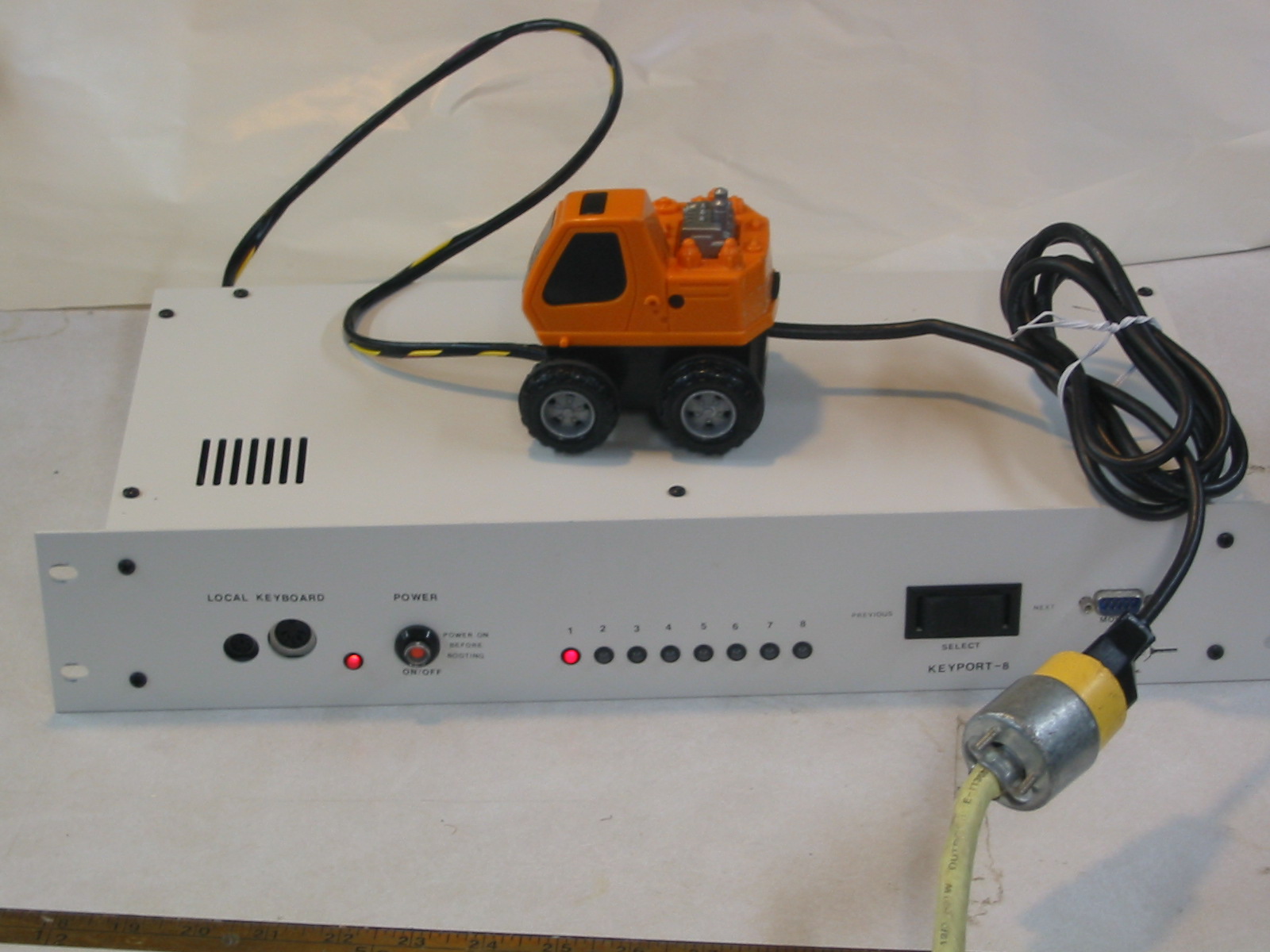
Submitted by amillar on Mon, 2005-08-29 06:49