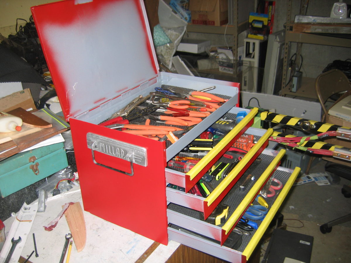
Over the years I have accumulated a growing pile of pliers, screwdrivers, wrenches, and other miscellaneous small tools. It long ago outgrew the little toolbox I have, turning into more of a tool pile or perhaps a tool dumping ground. I needed a new, bigger toolbox. Having recently built some new toys, namely a bending brake and spot welder, I knew I needed to build my own toolbox.
Over the years I have accumulated a growing pile of pliers, screwdrivers, wrenches, and other miscellaneous small tools. It long ago outgrew the little toolbox I have, turning into more of a tool pile or perhaps a tool dumping ground. I needed a new, bigger toolbox. Having recently built some new toys, namely a bending brake and spot welder, I knew I needed to build my own toolbox.
Actually, it was the other way around. I had the toolbox idea first. I built the brake and spotwelder because I thought they could help build the toolbox. And they did.
I gave myself a challenge on this project, to make the entire toolbox from reused and recycled materials. Not because I’m a cheap bas bargain hunter (I blame my dad’s thrifty Scottish upbringing… Hi Dad!), but because I’m really one of those eco-hipster tree huggers who wants to save my wallet the planet.
I wanted to make some metal boxes and trays. I have plenty of scrap sheet metal from things like old PC cases and microwave ovens. I already built a sheet metal bending brake. Now I just need a way to fasten parts together. Something easier than drilling a bunch of holes and screwing or pop-riveting. Something less messy than soldering or glueing. Something where I can just magically zap the parts and have them stick together instantly. Eureka! Spot welding. Time to dig through Google. And the trash can.
initial assembly
The internet has lots of articles about how to make your own spot welder, so I’m not going to repeat everything here. The first article that inspired me was the spot welder on Hack-A-Day. There are plenty of other home made spot welder articles out there too.
Basic Design
The basic idea in spot welding is to send a high electrical current (amperage) through two pieces of sheet metal, which will heat them up enough to melt a little spot and stick them together (the “bead”). We produce the high current with a transformer, which changes high voltage low current from the wall outlet into low voltage high current in the work piece. The heat comes from electrical resistance. You need low resistance metals in your spot welder parts (copper and aluminum) so you can create heat in a higher resistance metal (steel). So this spot welder is really primarily for welding steel. Which is OK since that’s what the vast majority of scrap sheet metal is anyways. At least mine is. If you have access to some secret stash of cast-off titanium, you’ll have to figure that one out for yourself.
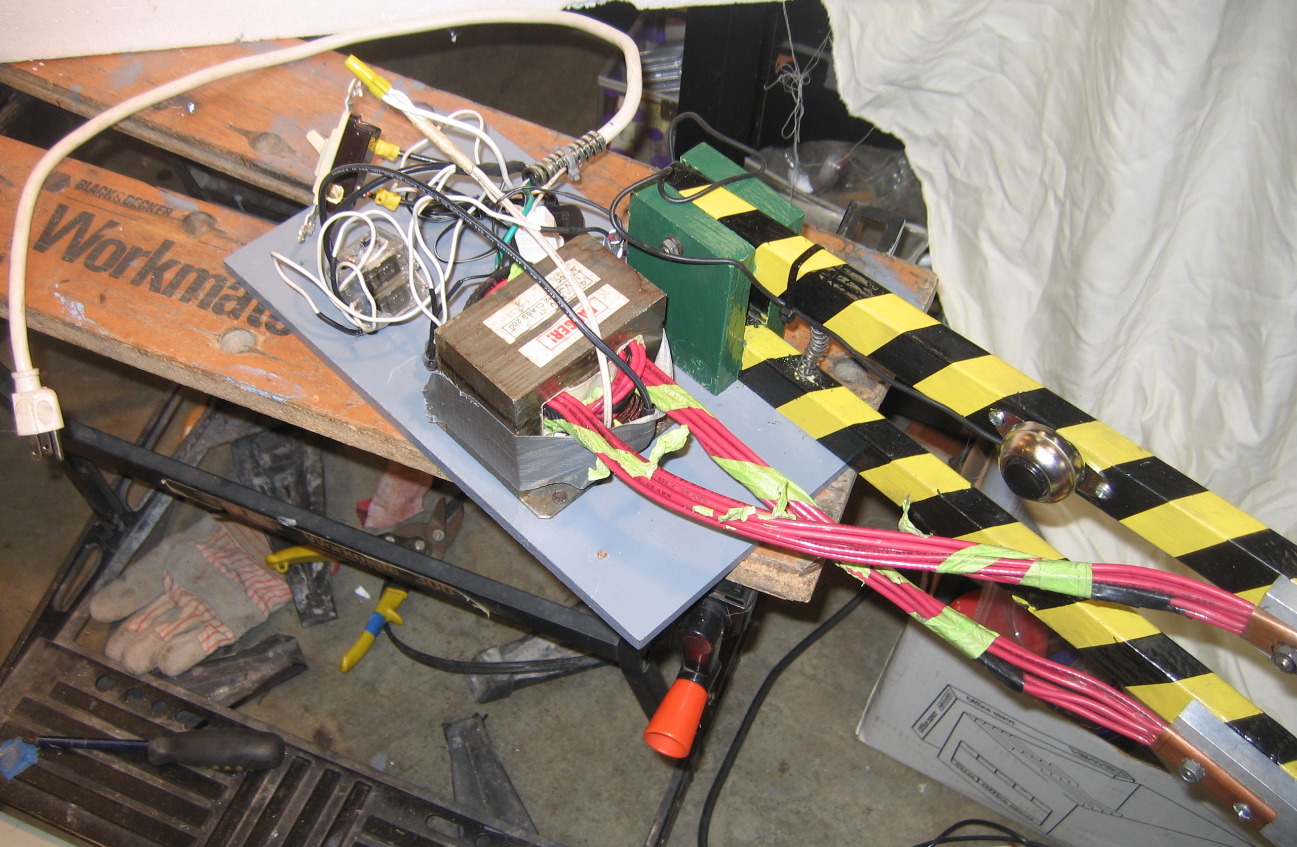
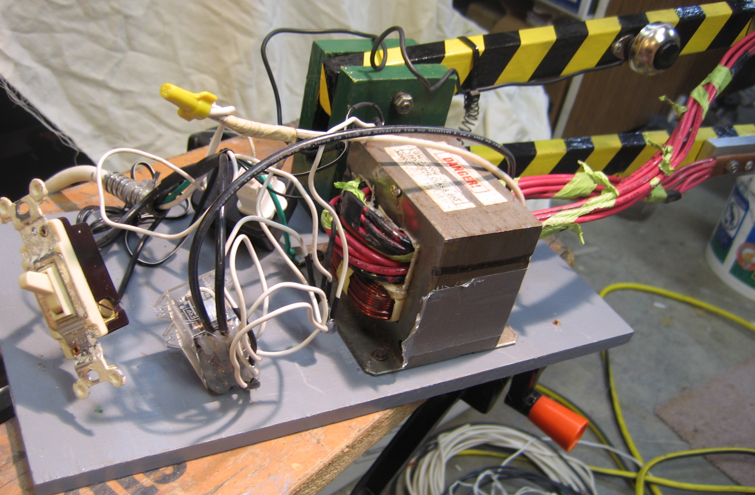
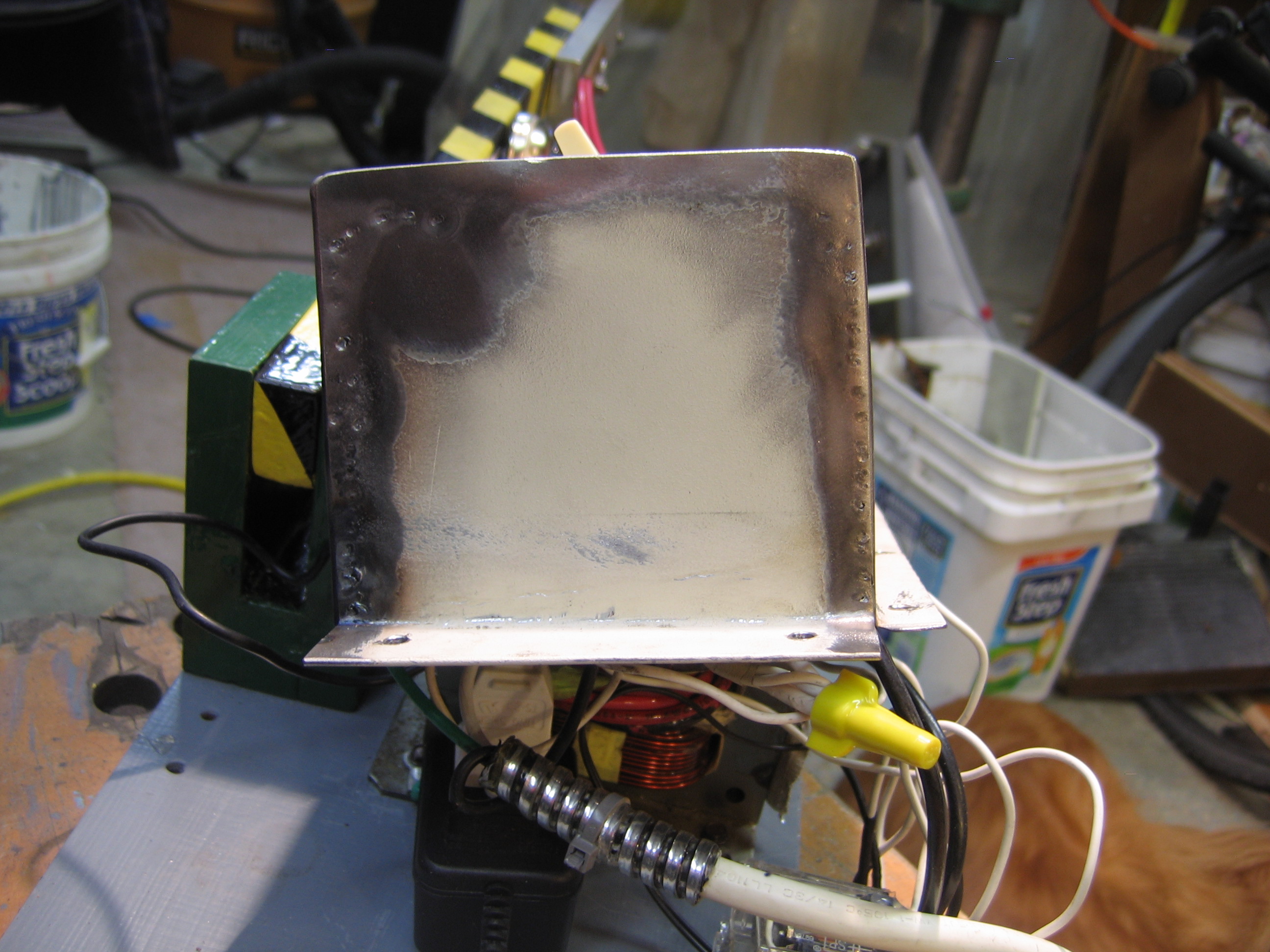
I needed a big, cheap transformer. Fortunately this is available in any discarded microwave oven. I can’t remember if my transformer came from the microwave oven left by the apartment dumpster, or the one left on the curb near the park. But you can probably find an unwanted, unloved microwave somewhere and give it new meaning for life. Or something like that.
Microwave ovens step up the voltage inside, but we want to step it down. So we remove the transformer secondary winding, with the lots and lots of turns of teeny-tiny little wire, and replace it with a few turns of big fat wire. I used a hack saw to cut off the old wire. You can try that or your teeth, but I’d recommend the hacksaw.
Wire size is dictated by the current, so we want as big a cross-section as possible in our wire. I used eight strands of 10-gauge (AWG) stranded copper wire, which the building electricians at work let me have when they were ripping out some old light fixtures. 10-gauge wire has a cross-section area of 5 mm sq., so that puts me at 40mm sq. for all eight strands. Those hot-shots in the other articles bragging about their 4-gauge wire? I got double the size. Oh yeah, who rules now, huh? HUH?!?! Oops, sorry, got carried away with the nerd contest there for a moment. Where was I?
I wound one and a half turns of the wire, which was all I could fit. Measuring with my volt meter, I found that with 120 VAC input, I measured 2 volts on the output (open circuit with no load). When welding a bead, the 2 volts dropped to 0.5 volts. And the current? Using my inductive ammeter, I measured 15 amps on the input (mains) side, and 900 amps on the output side. Let me just say: it’s awesome.
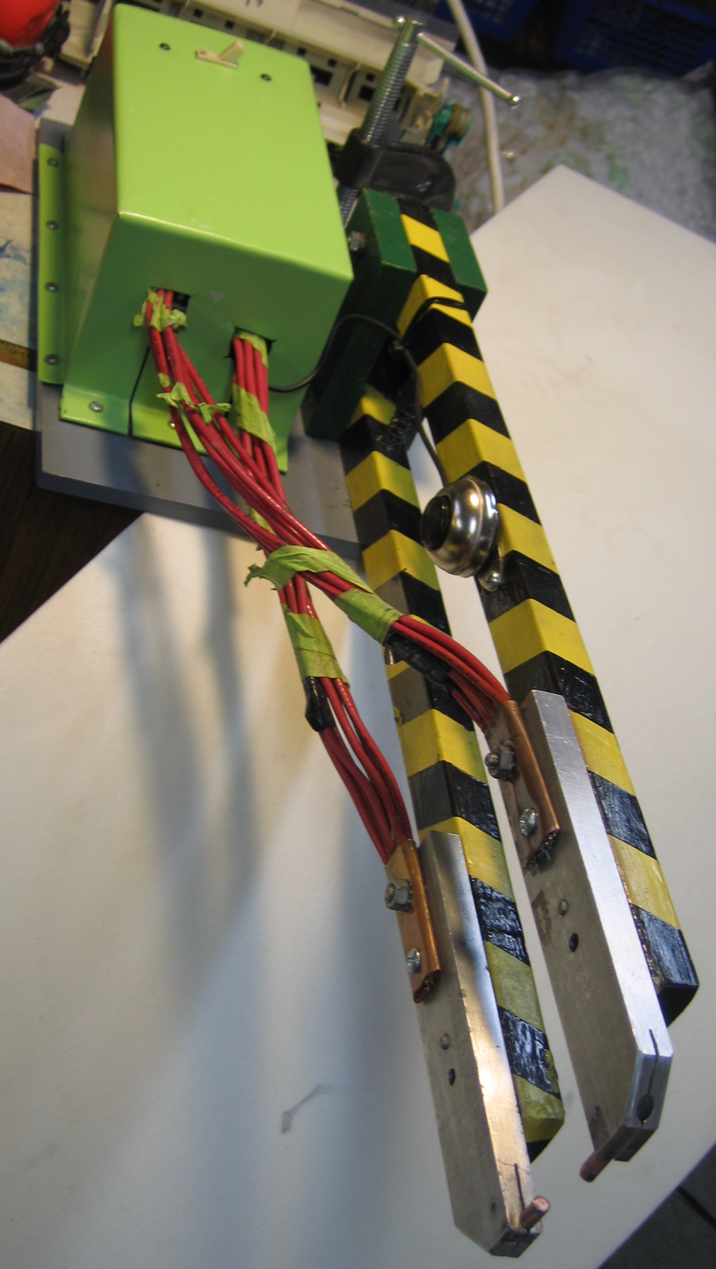
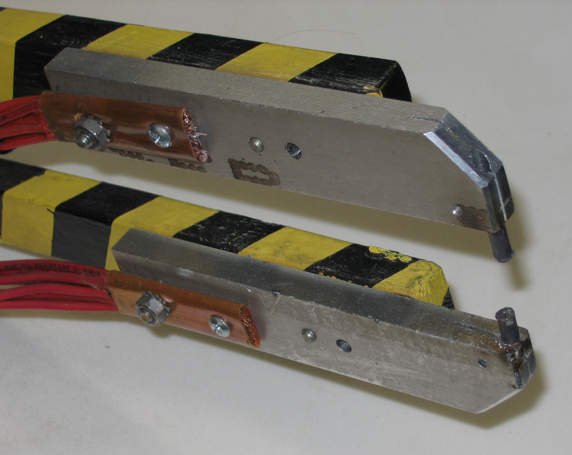
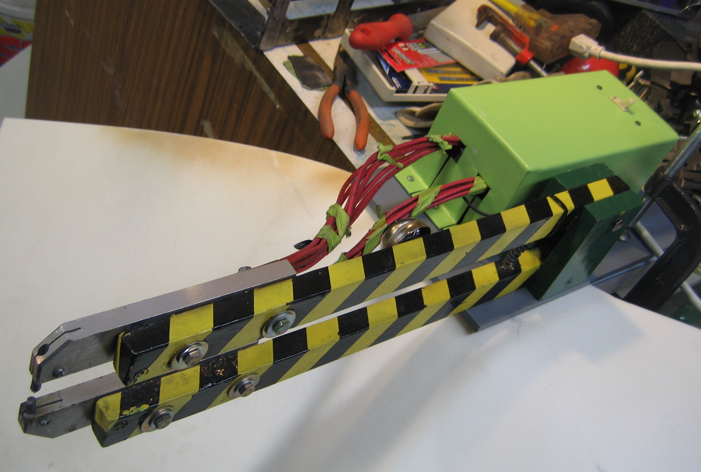
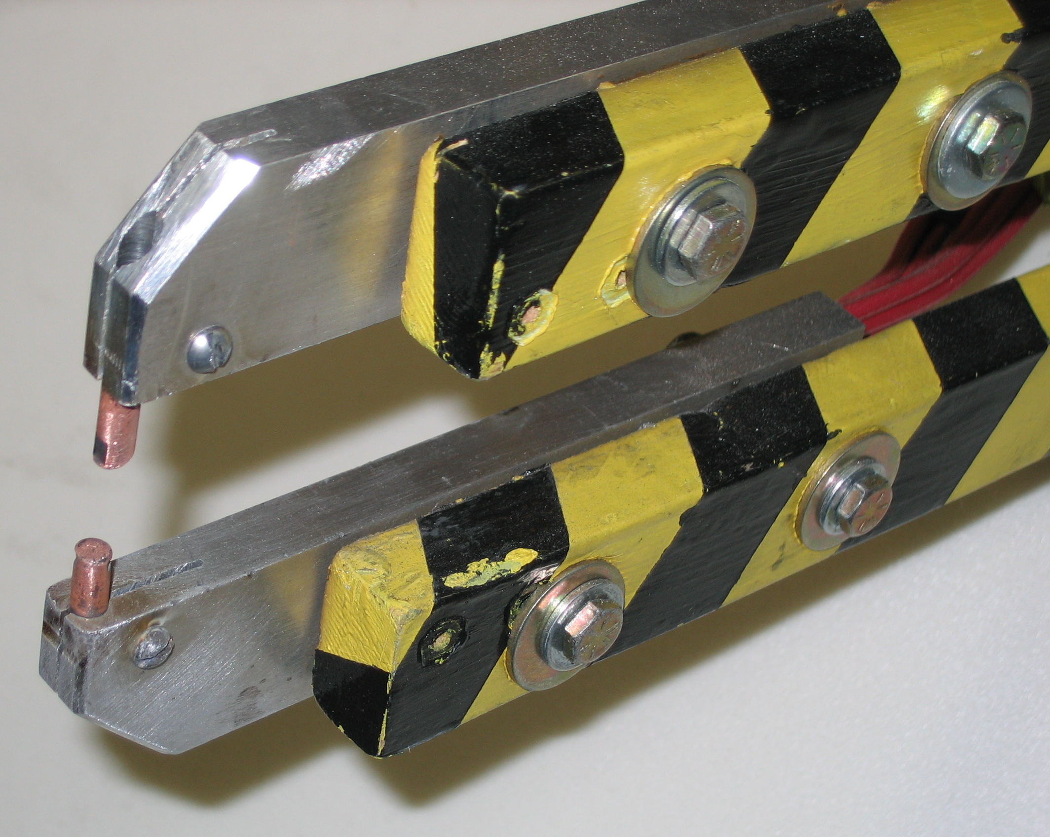
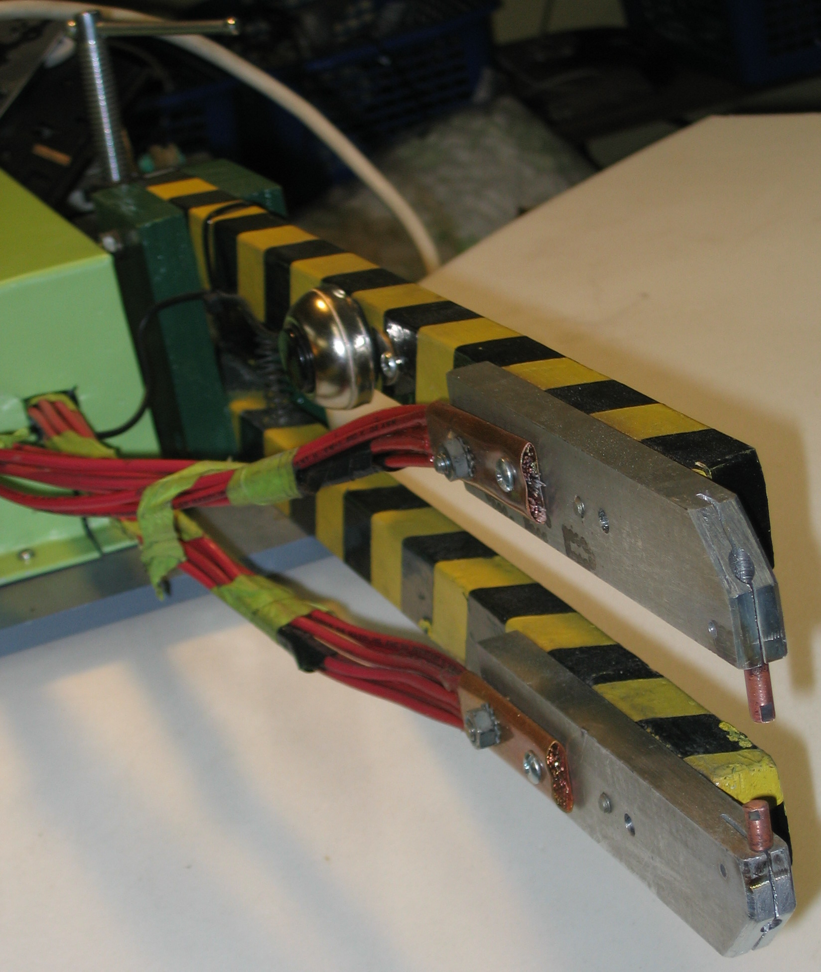
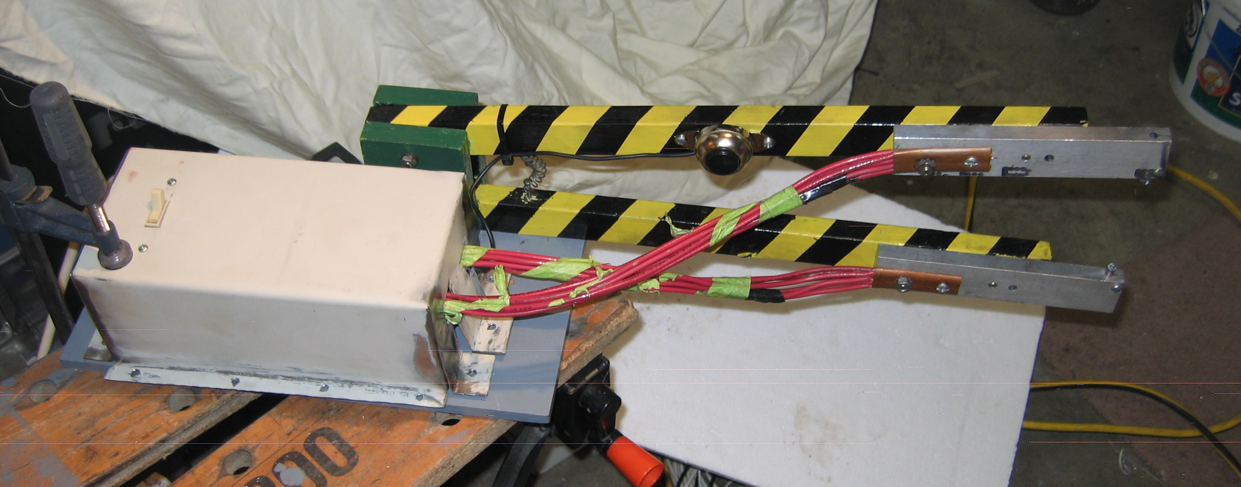
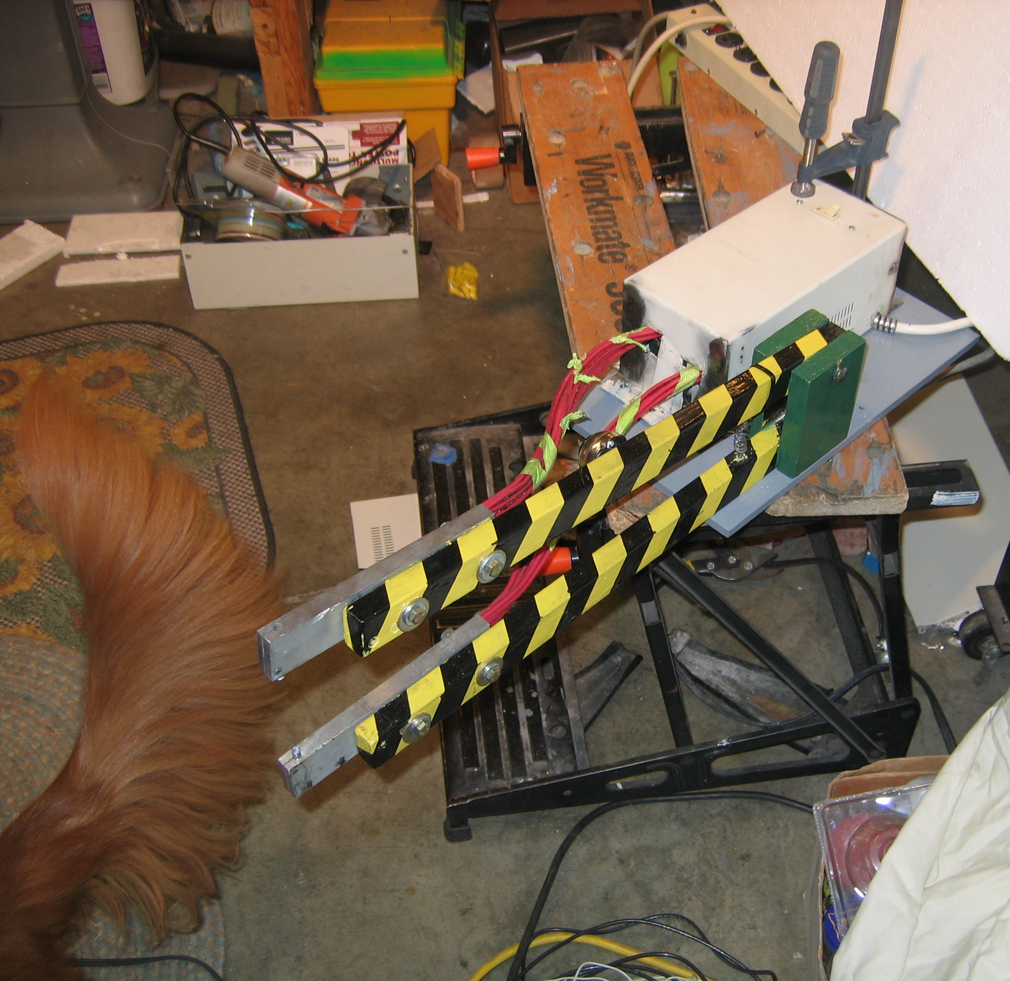
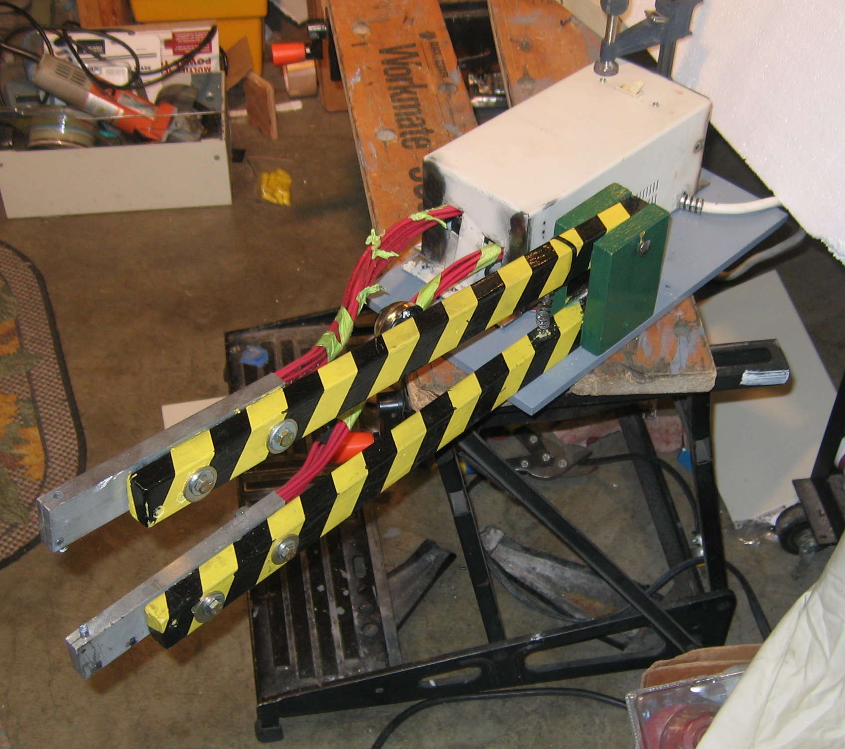
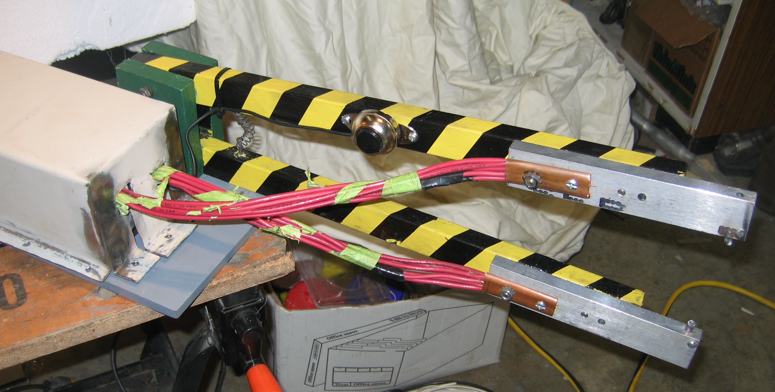
Mechanically, the design is simple. Two identical wooden arms held open by a spring. Each arm has an aluminum bar on the end, holding a copper electrode. The wire from the transformer is attached to the aluminum bar, with as much surface contact area as possible. I stripped the ends of the wires and smashed, I mean crimped, a piece of copper plumbing pipe onto the end to make a lug, and bolted it to the bar. (Actually, the first time I squeezed the pipe so tight that the side split open. The second time I got it tight enough to hold on to the wire but not split apart. No, that wasn’t admitting a mistake, that was a “design revision”. Yeah, that’s my story, yeah…)
The electrode tips are MIG welding tips, which are adequate although possibly a little short, depending on what you are doing. But they are inexpensive, which you probably know by now is one of my top criteria.
jaws and electrodes
jaws and electrodesjaws and electrodes
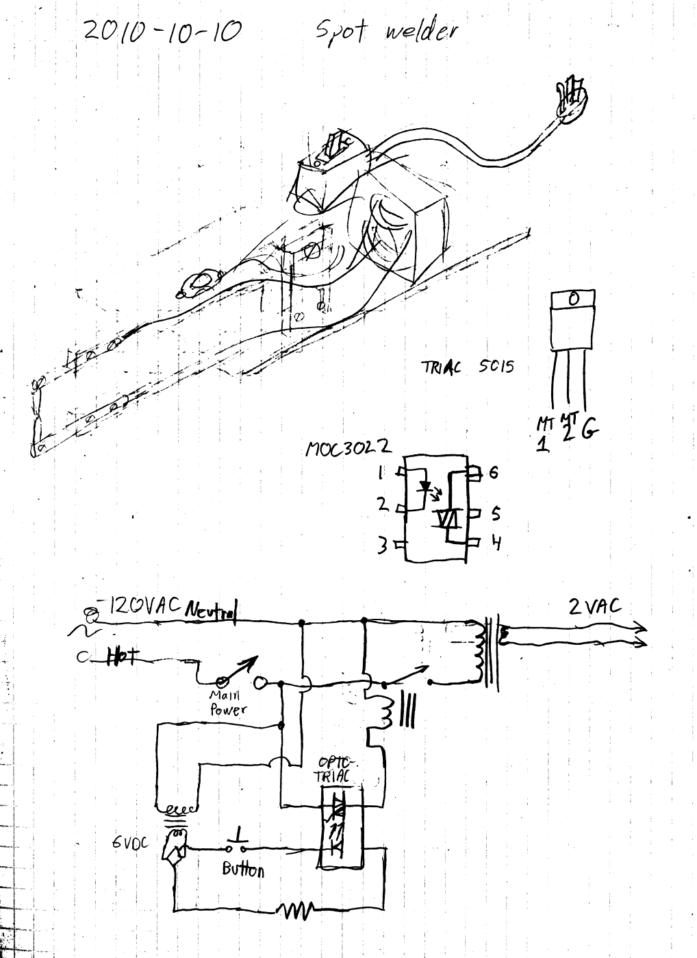
My control circuit
internalsschematic
I needed a push-button switch on the upper arm, because I am all about elegance and comfort. Hold the arm down on the work piece, push the button until the acrid burning paint smoke burns my nostrils, I mean until the spot weld bead is formed, release the button, and then release the arm. (Just kidding on the smoke part; I always clean the weld area thoroughly to remove paint and contamination before attempting to weld it. Well, usually.)
internals
As far as safety goes, the spot welder is pretty safe. At a few volts, there is no concern of electrocution on the secondary output side of the transformer, the arms or electrodes. The main concern there is burning yourself on a hot piece of metal.
The primary input side of the transformer is another story. This thing works from 120VAC electrical mains, and I’m building it myself (that should scare you enough right there), so yes I’m a little leery about having high voltage right next to my finger on the push-button. My solution was to use a low-voltage control circuit. The push button operates at 6 volts, and activates a mechanical relay, which switches the 120 volt input to the transformer. I used a common “wall-wart” power adapter to provide the 6 volts. There is also a master on-off switch, for extra safety.
One possible concern with using mechanical relays is that arcing of the contacts can cause pitting and deterioration over time. This can be reduced by using larger contacts (in relays with higher amperage ratings). It can also be reduced by using solid state relays, but those cost more than, like, one dollar, so they exceeded my budget for this project. Since I knew I was drawing about 15 amps on the input side, I wanted my relay switching to be rated for much more than that, for safety and longevity. I got two double-pole relays rated at 12 amps, and wired all 4 poles in parallel. This gave me 48 amps nominal rating, which is safely far beyond my expected usage of 15 amps.
I added one more minor complication to the control circuit. I did not have any mechanical relays with low-voltage (6 volt) coils and high-voltage (120 VAC) high amperage (10+ amps) contacts. The only relays I had with high-voltage contacts also had high voltage coils, so I used another transistor-like chip called a MOC3022 opto-triac to control the relay. The opto-triac takes a low voltage DC signal and switches a high voltage AC line. The switched high-voltage AC output of the opto-triac is very low current, so it is not adequate to switch the transformer directly, but it is perfectly fine for driving the relay coil. So the push button activates the opto-triac, the opto-triac activates the relay, and the relay activates the transformer. Why make it so complicated? Well, because it was really cheap. The opto-triac cost less than a dollar, and the relays were a dollar or so also. While a solid-state relay would have been nice, it would probably have cost about 30 dollars, which is about 29 dollars more than my budget for the project.
Case
case
With live, high-voltage electricity feeding the transformer and control circuit, the spot welder needs a case to cover those parts for safety. Having been suitably inspired by “Uncle Dave” Gingery to make my tools bootstrap themselves, I knew that my spot welder needed to make its own case. I cut and bent some scraps from a PC to make a cover for the transformer and wires. Then I used the spot welder to attach the end panel of the cover. Voila! The machine builds itself! Well, partly at least.
case (and my assistant Sam)case
spot welded its own case
Results
This thing works fairly well. I’ve mostly been using it on some salvaged sheet metal from a refrigerator door, and from PC cases. The thinner refrigerator door skin welds a good bead in 1 or 2 seconds. It measures about 0.025 inches thick (about 0.6 mm, or perhaps 25 gauge I think). The heavier PC case metal takes about 4 or 5 seconds to make a good bead. It measures about 0.040 inches (about 1 mm or perhaps 19 or 20 gauge I think).
The tips and big wires get fairly hot in use. If I weld PC case metal for 5 minutes straight, I need to stop and let the spot welder cool down for another 5 or 10 minutes. The arms themselves are wood, and remain quite cool to the touch. Wood seems to be a pretty good heat insulator.
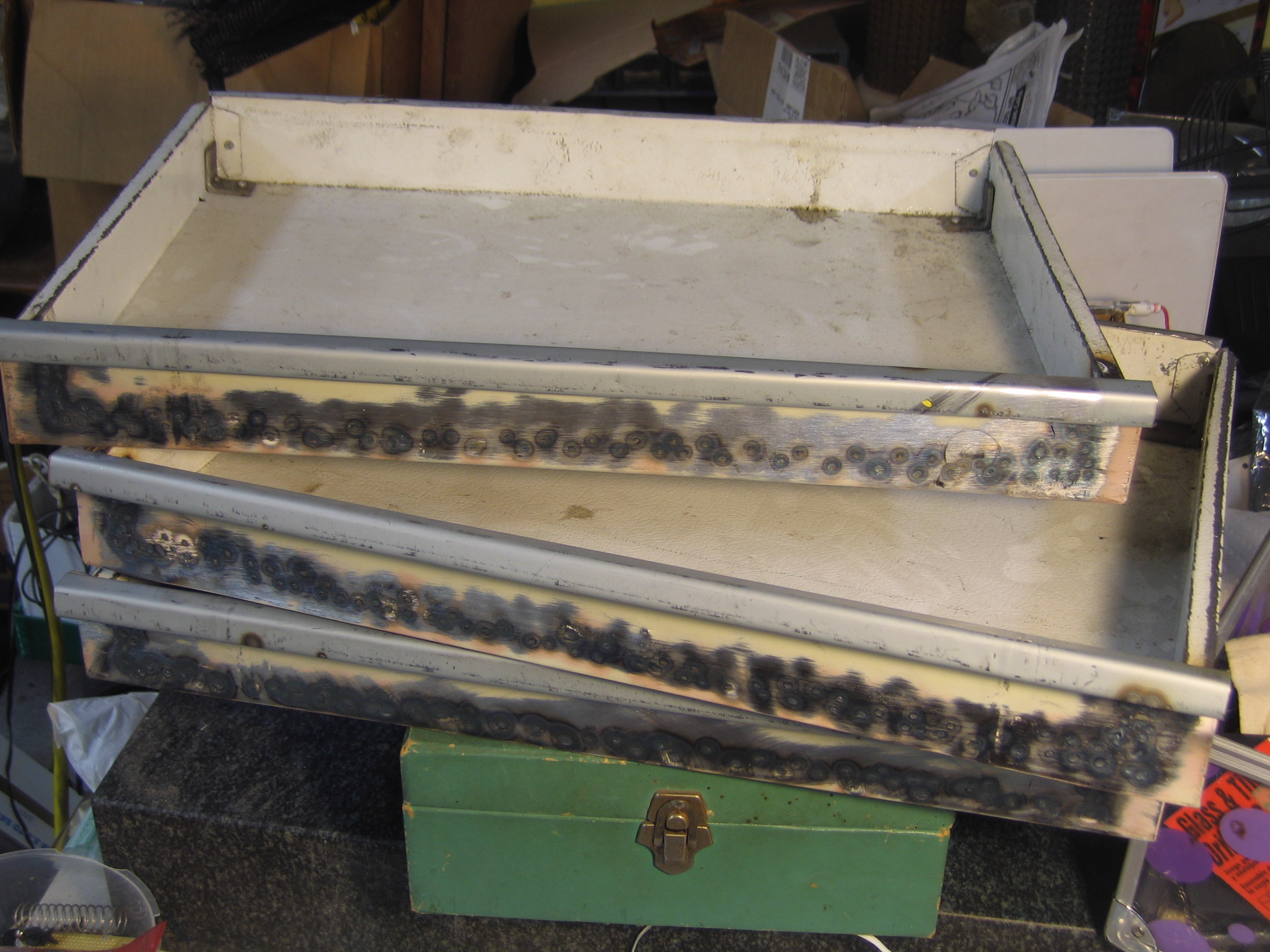
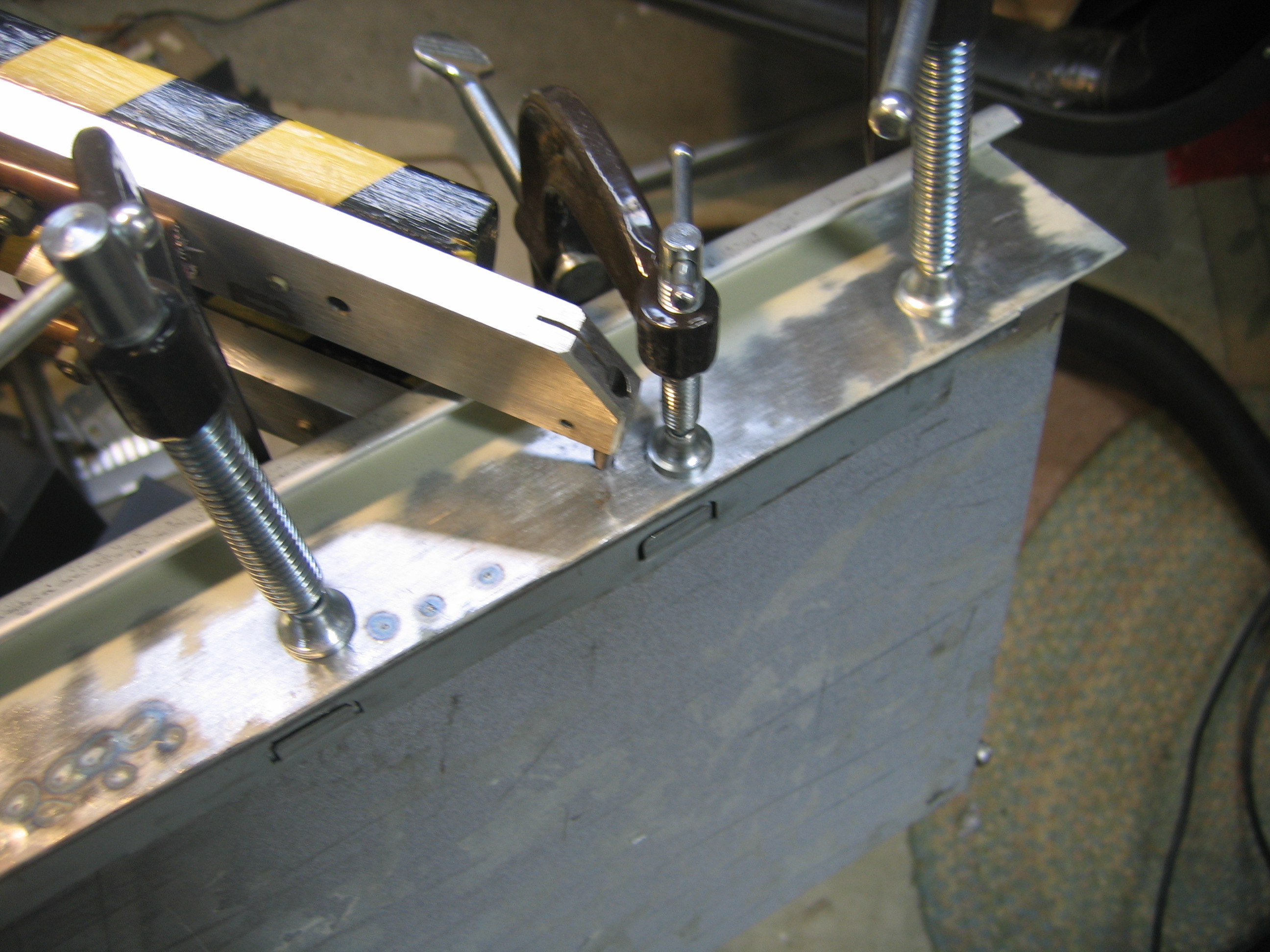
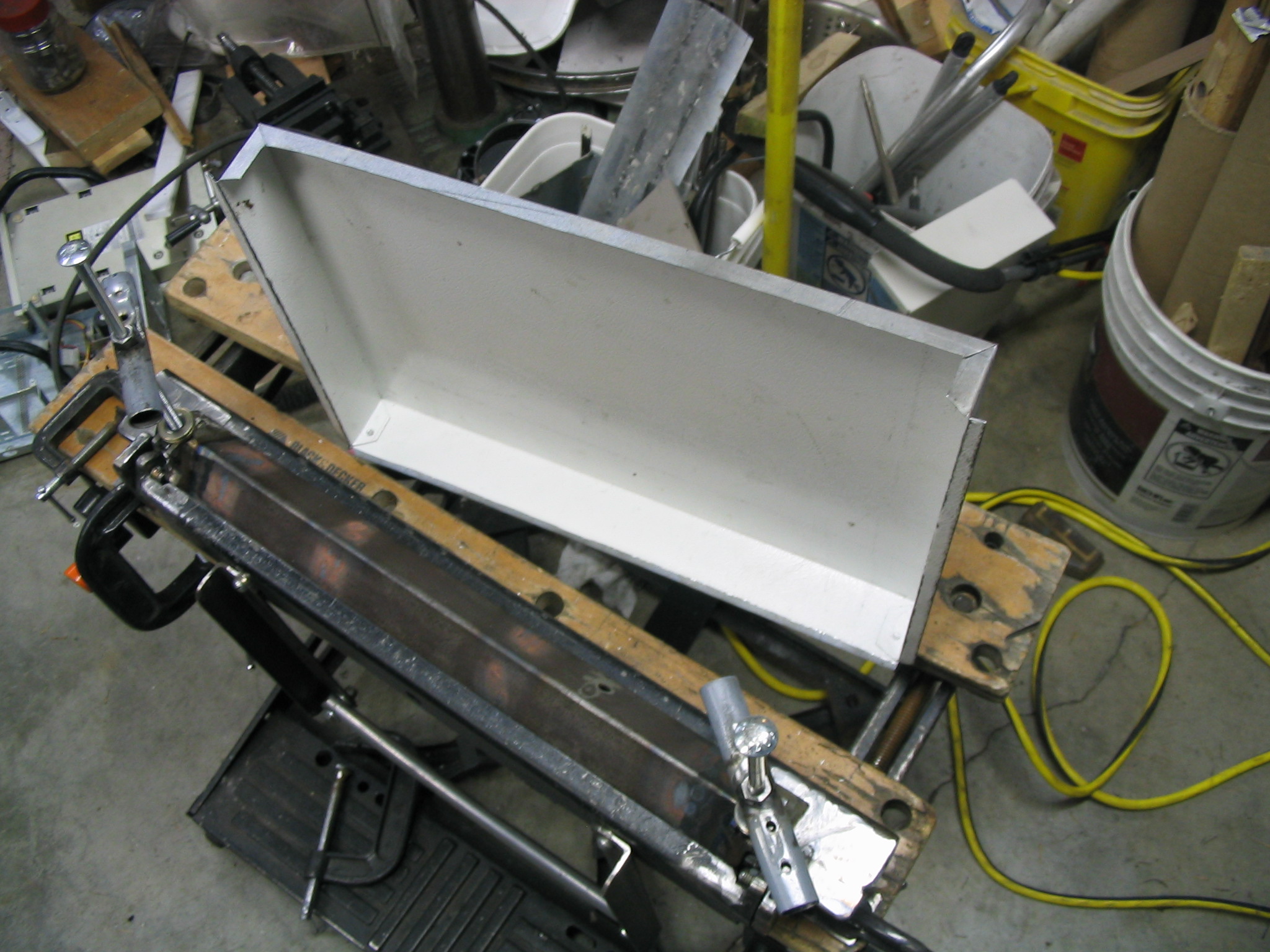
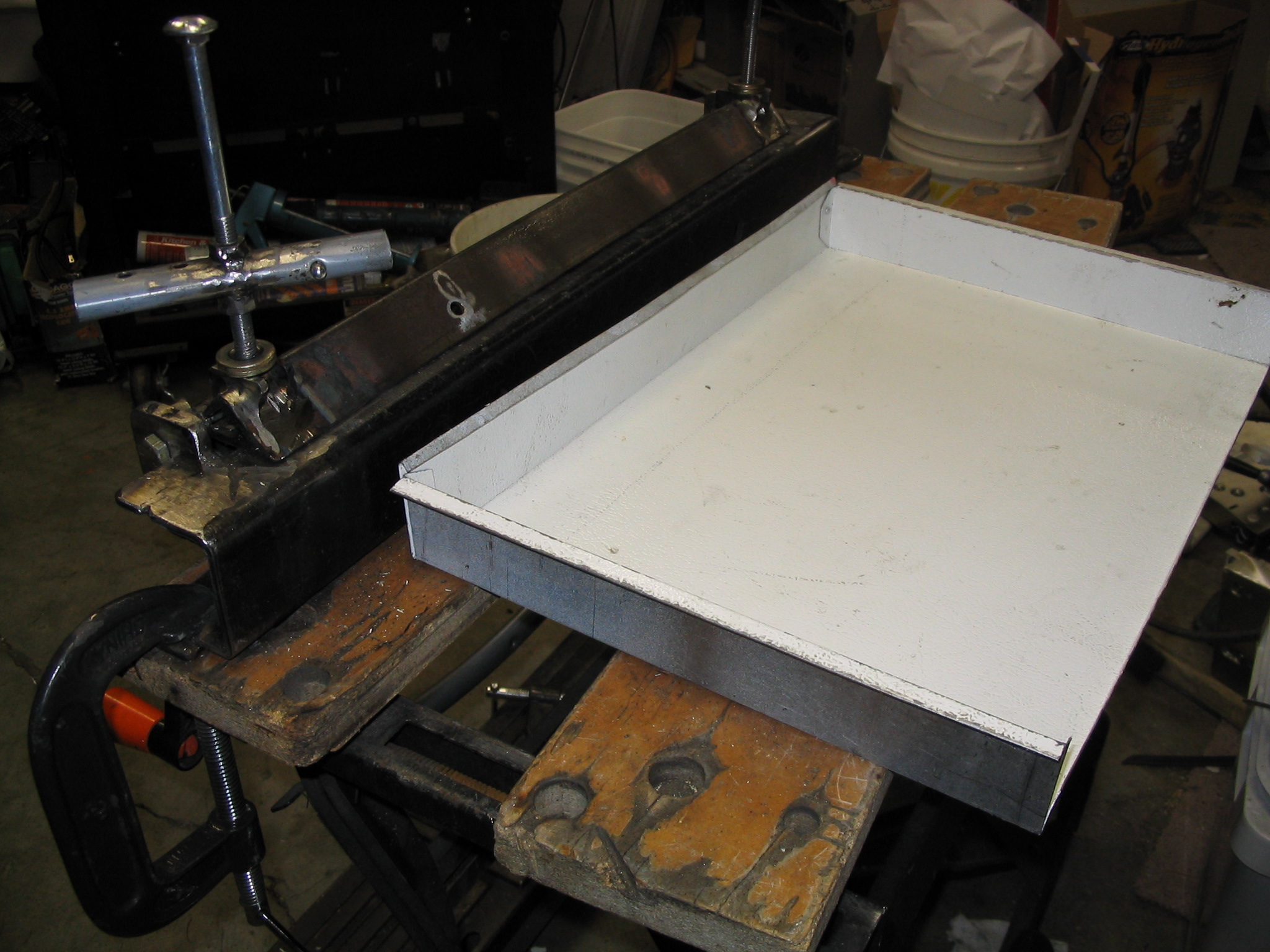
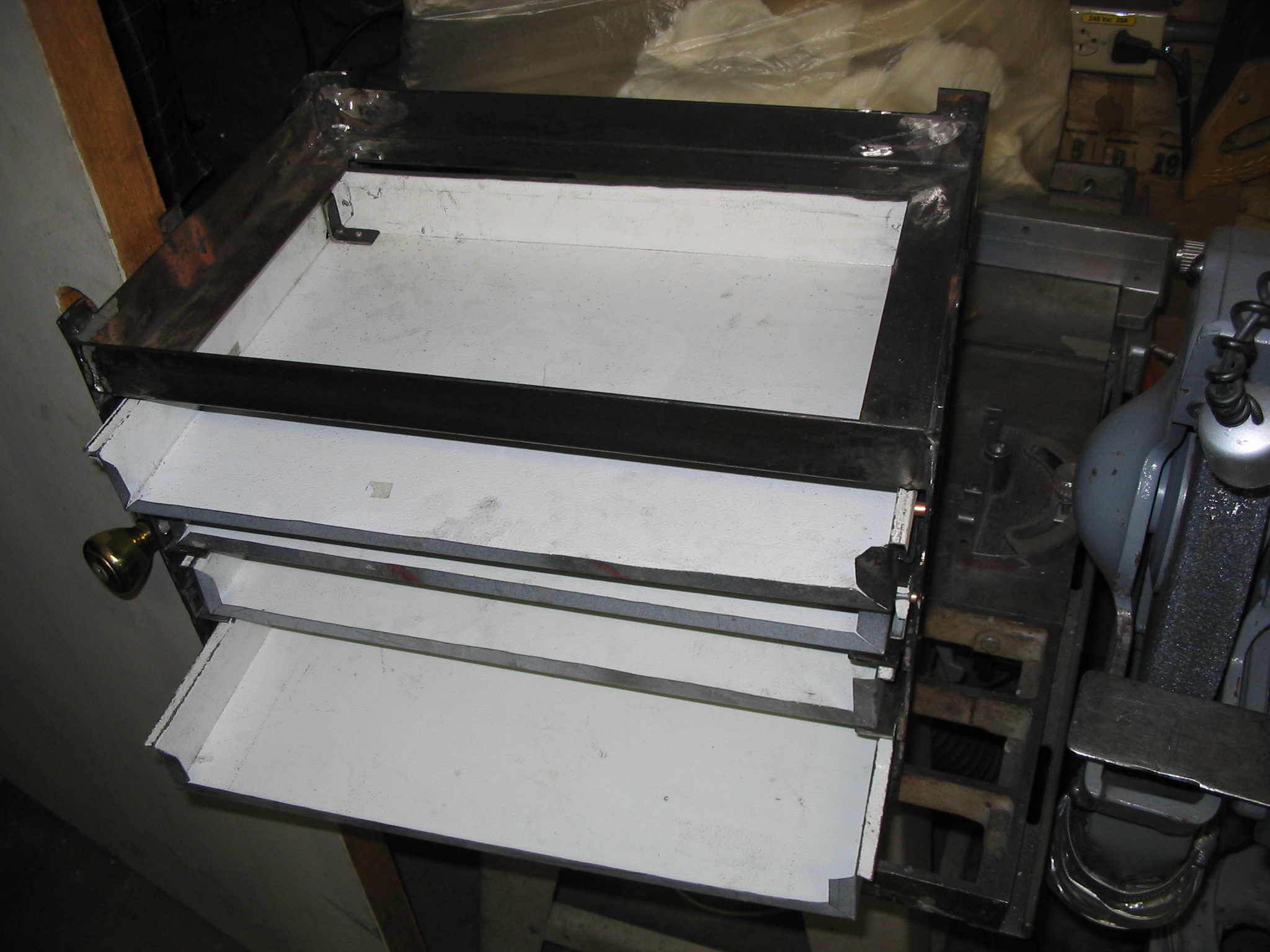
The first real project for the spot welder (not including making its own case) is attaching the drawer fronts of my tool-box-in-progress. I’ll finish it one of these days. In the mean time, I’m spot welding!
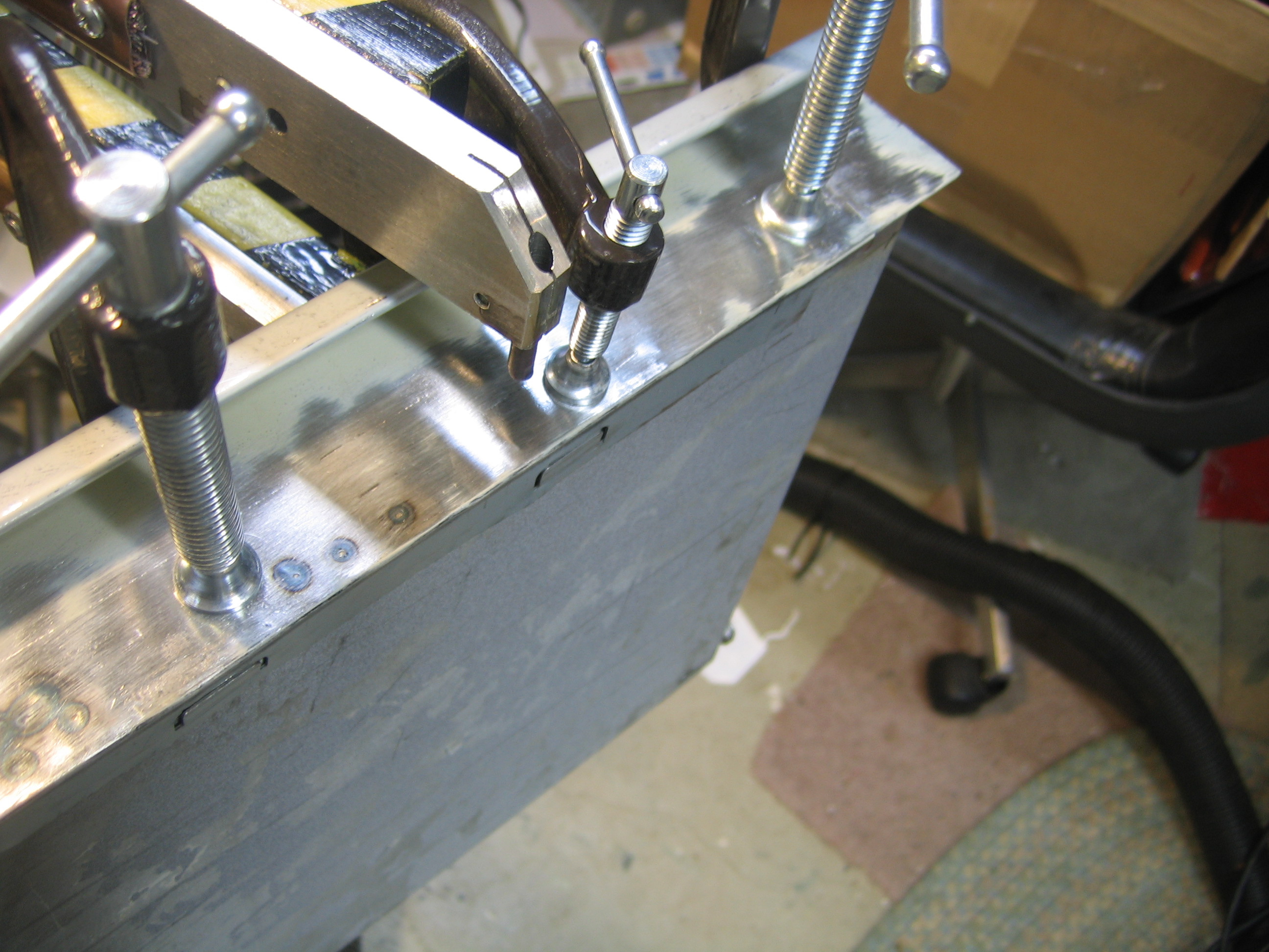
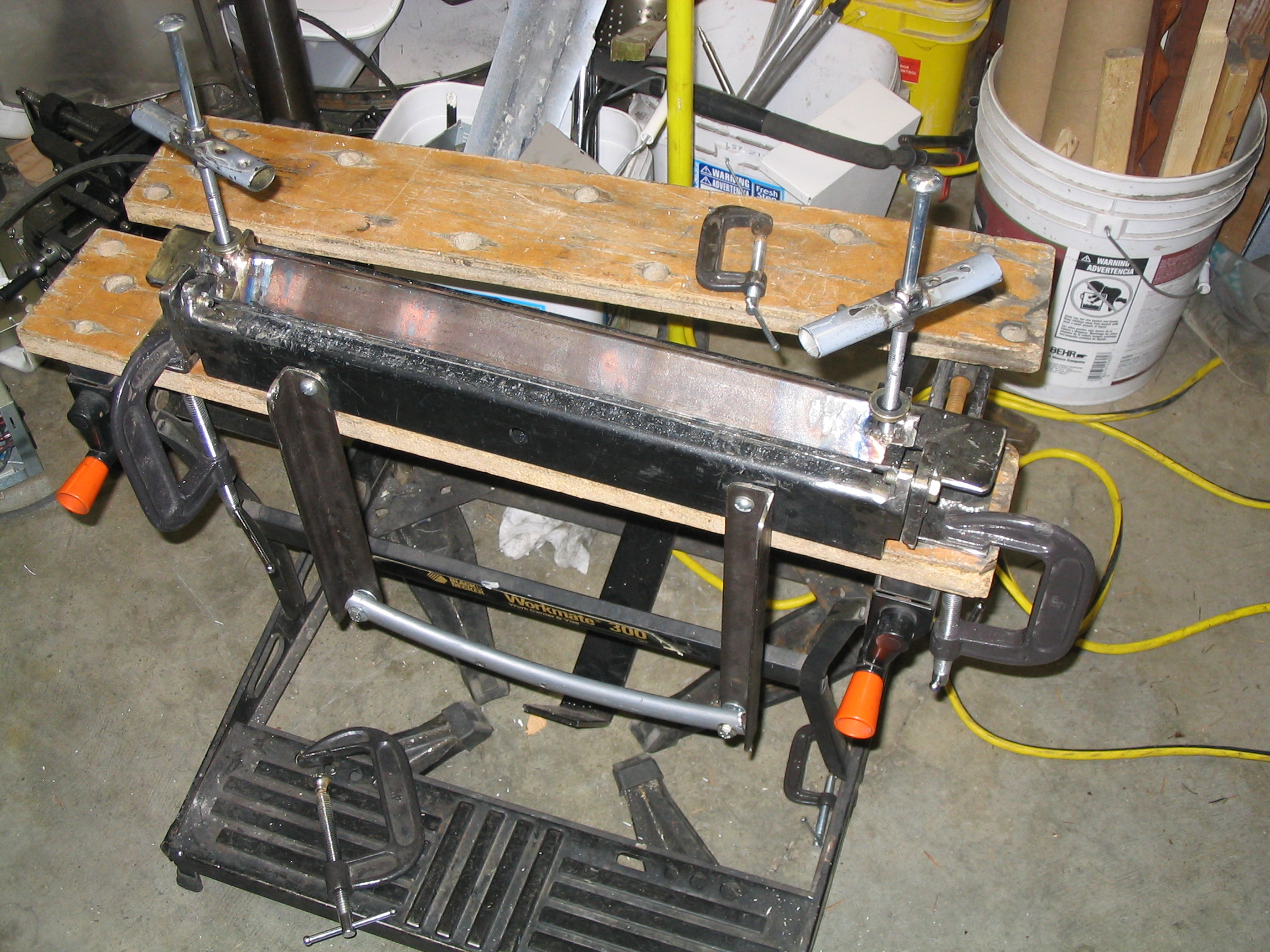
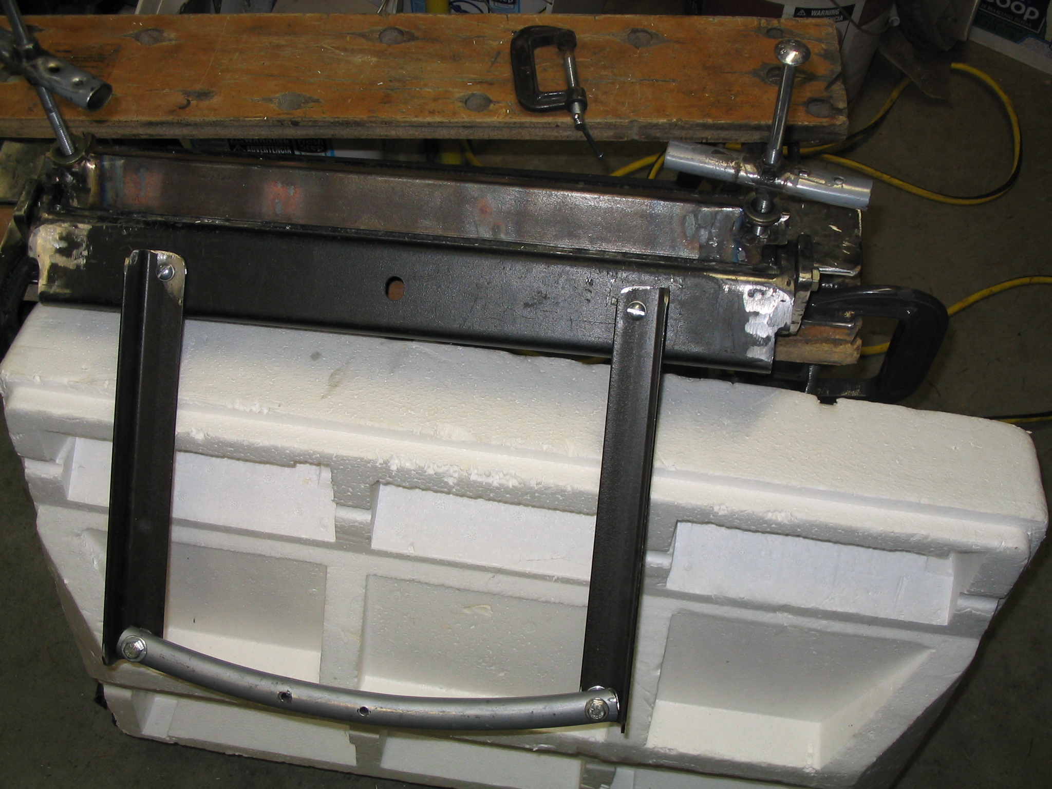
I built my own sheetmetal bending brake. I used some scrap angle steel pieces which I welded with my arc welder.
Scrap sheet metal is easy for me to find, from PC cases and discarded appliances. But to be useful, you need to be able to bend a nice clean straight line.
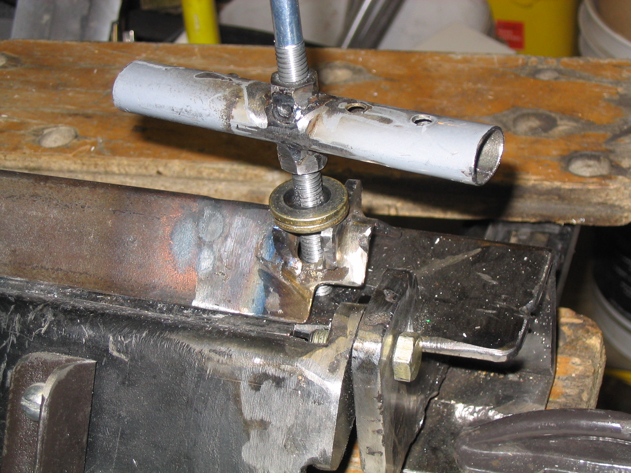
The base and bending lip were easy to make. I had a little more trouble deciding how to make the press clamp. My short-term solution just bolts straight down from the top.