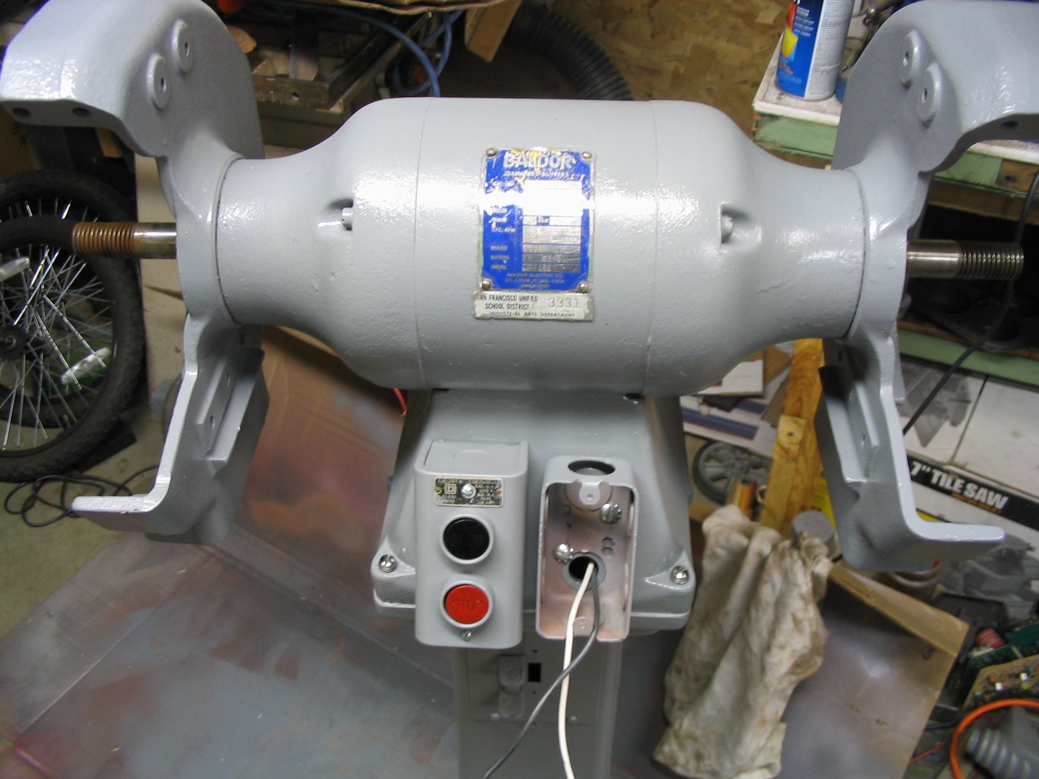
 I received a Baldor metal grinder with 10-inch wheels, with a motor wired for three-phase industrial power. Three-phase power is not provided in U.S. residential homes, so I needed to power it from normal single-phase power. My solution was to build a balanced static phase converter, requiring only a few relatively inexpensive capacitors. (Much less expensive than the nuclear reactor I was considering.)
Research and Testing
Electric Motors in the Home Workshop Amazon IndieBound |
I knew I had some homework to do, to figure out how to make this work. I had ignored much information on 3-phase motors in the past, thinking that I would likely never need it. When would I ever come across any 3-phase equipment that would fit my miserly budget? Well, now, it seems.
The first resource I turned to was Electric Motors in the Home Workshop by Jim Cox, my favorite book on the subject. This book is written specifically to address reusing various industrial and appliance motors for home-built tools and uses, which fits my crazy schemes. It covered the basics of 3-phase motors, but did not go into great details. It did describe a very common method of generating 3-phase power from single phase, which is called a rotary phase converter. In this method, you use a single-phase motor to mechanically drive a 3-phase “idler motor” which generates the other 2 phases. This is a robust and flexible method which can handle multiple varying 3-phase loads. It also takes up some room, and requires two large electric motors dedicated to it. If you had a variety of 3-phase motors to run, it is a good solution. But it seemed like overkill for just my one grinder.
 I did some more Internet searching, and came across another idea: the static phase converter. This is a very simple converter which uses capacitors matched to the amperage draw of the motor to generate the extra two phases. As long as your amperage draw does not vary much (meaning you can only really use it for one motor), this is a simple and inexpensive solution to the problem.
I found the best explanation and description in Rick Christopherson’s page on
building a balanced static phase converter. I used his guidelines to determine the likely capacitor values I would need for my converter.
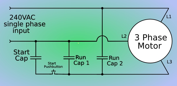
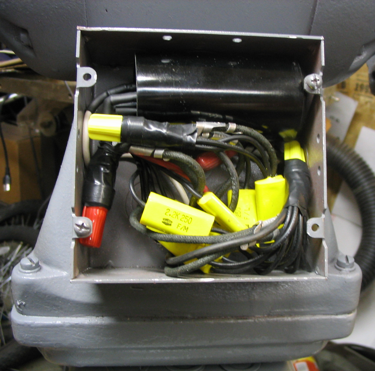
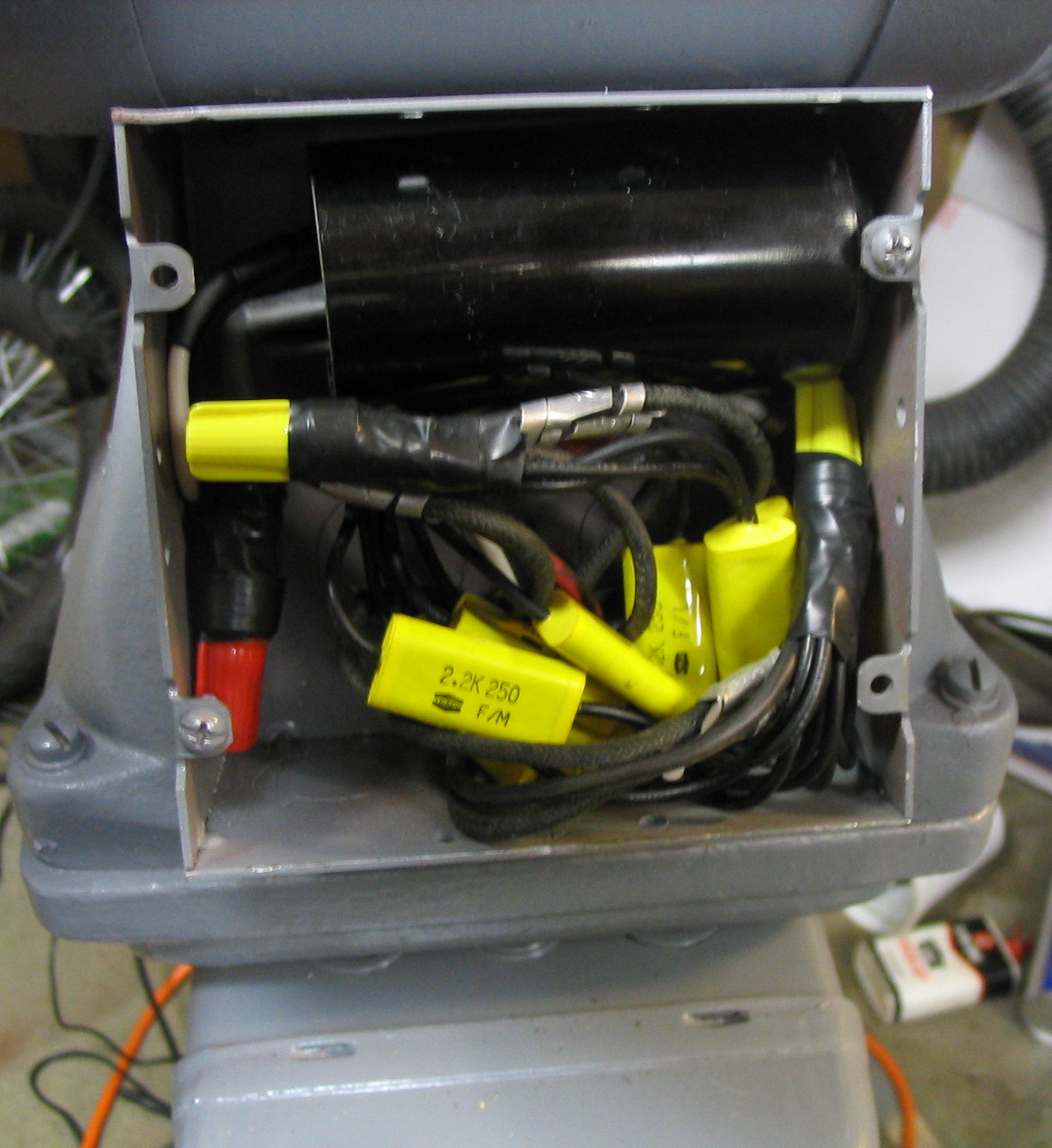
There are two run capacitors for the extra two phases. The two capacitors create pulses 120 and 240 degrees out of phase with the primary, so the second capacitor is twice the size of the first. Based on his tables, I guessed that my motor would require about 6 uF and 12 uF for the two phases.
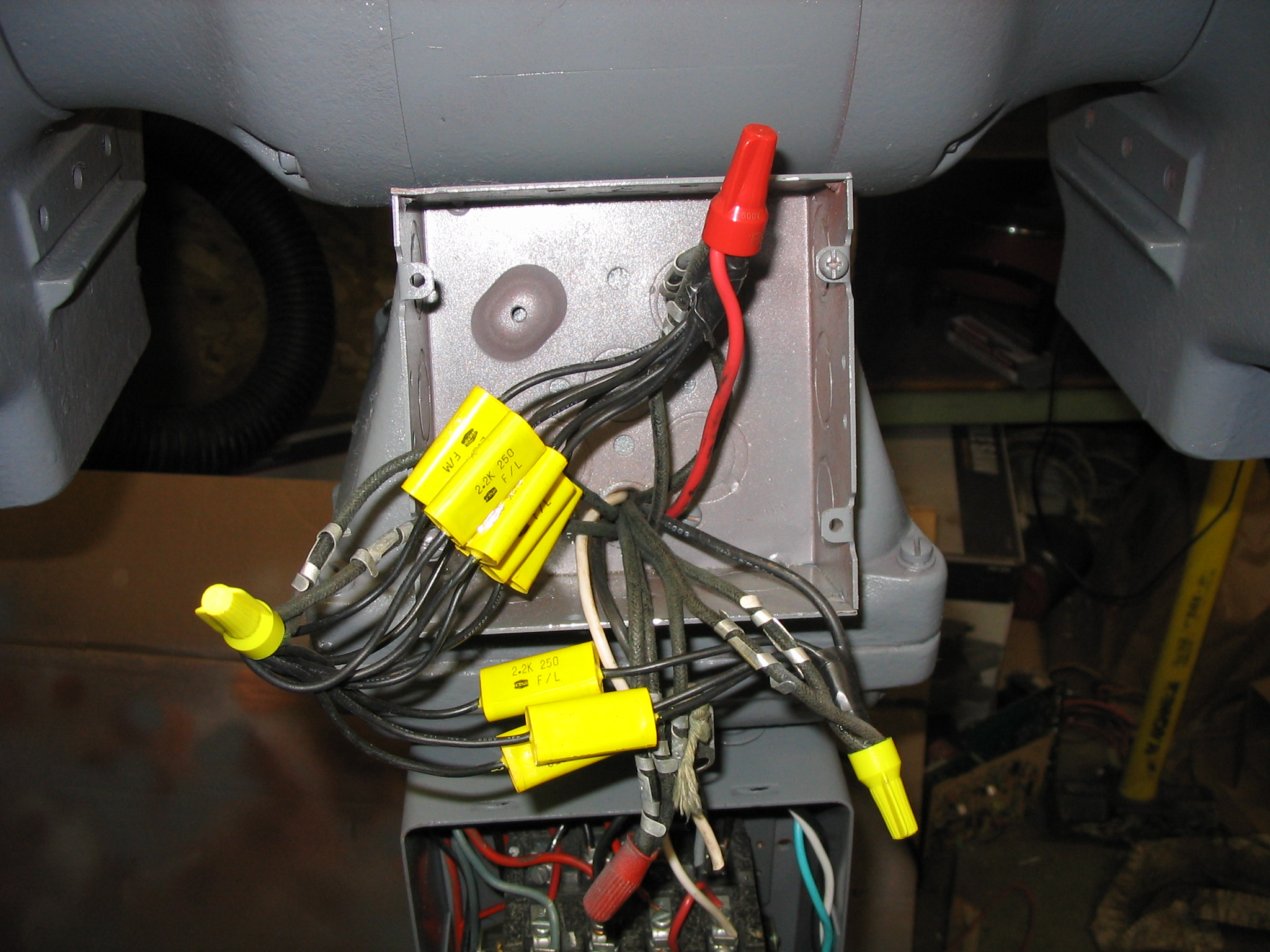
I went to a local surplus store, and was able to find smaller capacitors of 2.2 uF. My electricity textbook said that capacitors can be combined in parallel to add them up, so I just combined 3 for one phase and 6 for the other, providing 6.6 uF and 13.2 uF.
Just putting the run capacitors in the circuit would get it to run, but it would not start from a stand-still. With my dad helping me, we were able to spin the motor axle with a rope to get it started, and then turn on the power to make it continue running. It worked! I checked the power draw of all 3 phases with an inductive ammeter, and they were all nearly identical within 0.2 amps of each other.
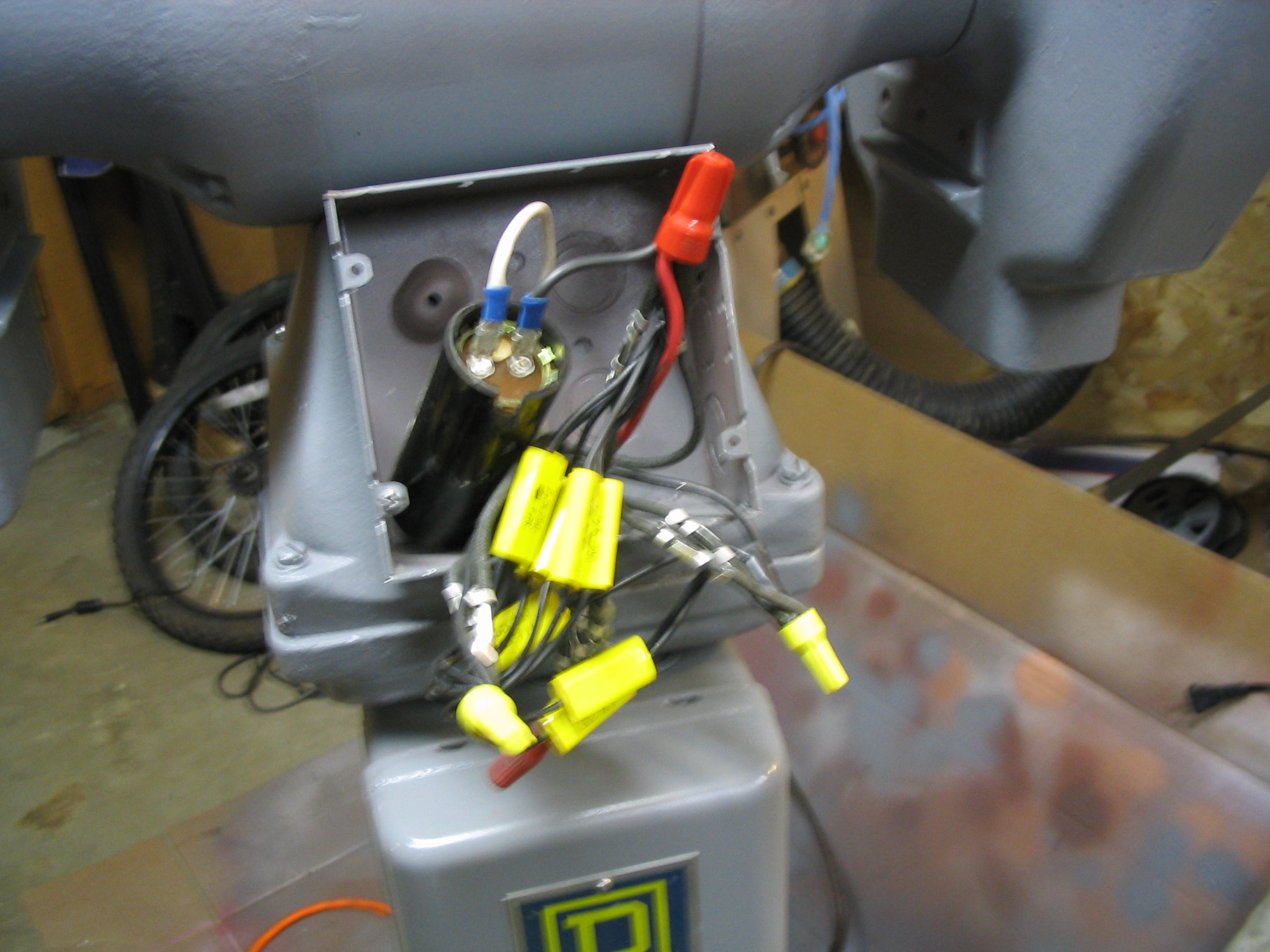
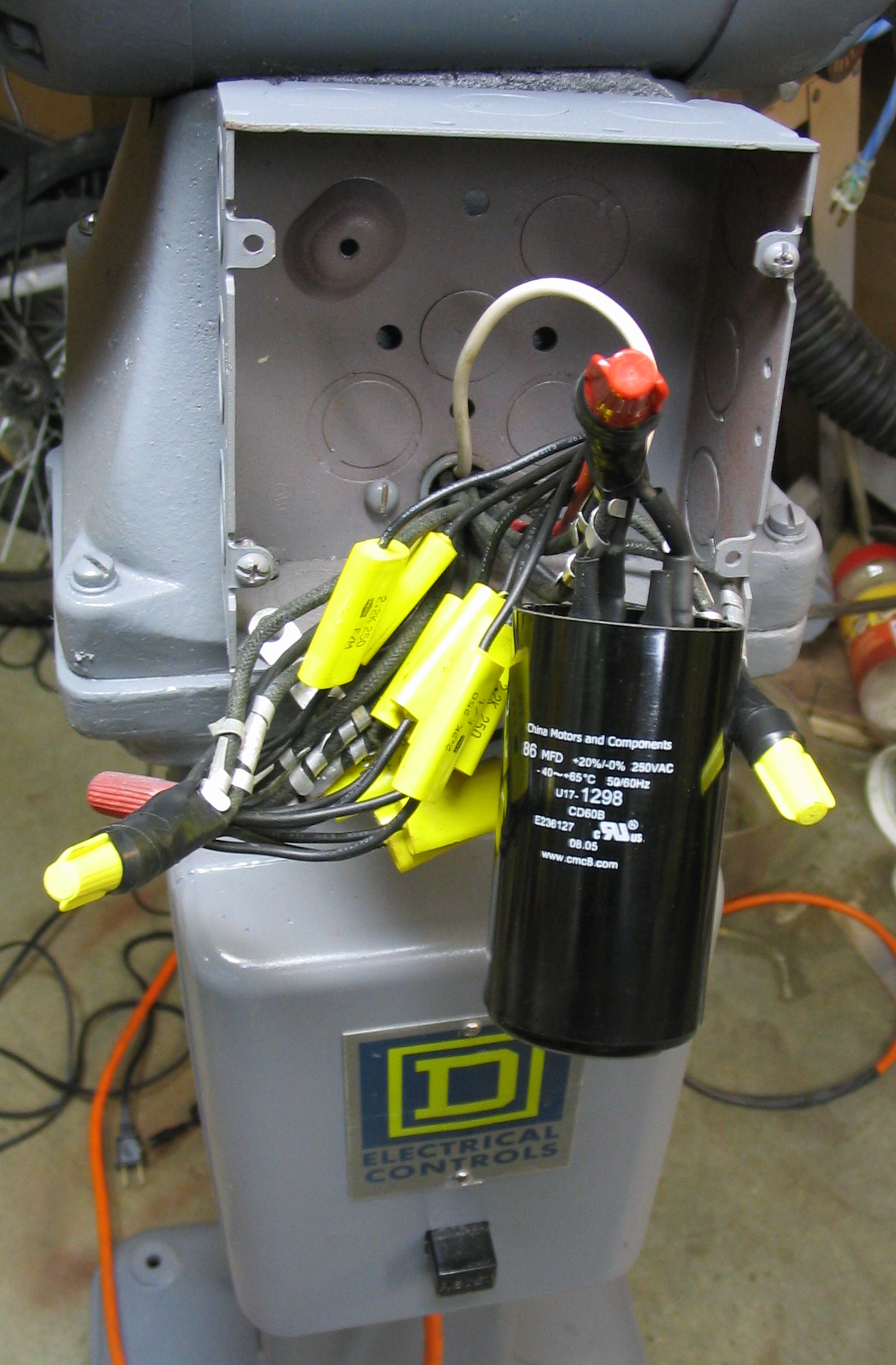 To bring the motor up to speed under power, it needs a large starting capacitor, connected in with a momentary push button. They are readily available, sold simply as A/C start capacitors. I had a capacitor from an old washing machine motor, which worked to start it as a test. I ordered another one of 86 uF from an Internet mail-order surplus place. Holding the start button for about 3 or 4 seconds is all that is needed to bring the motor up to full speed.
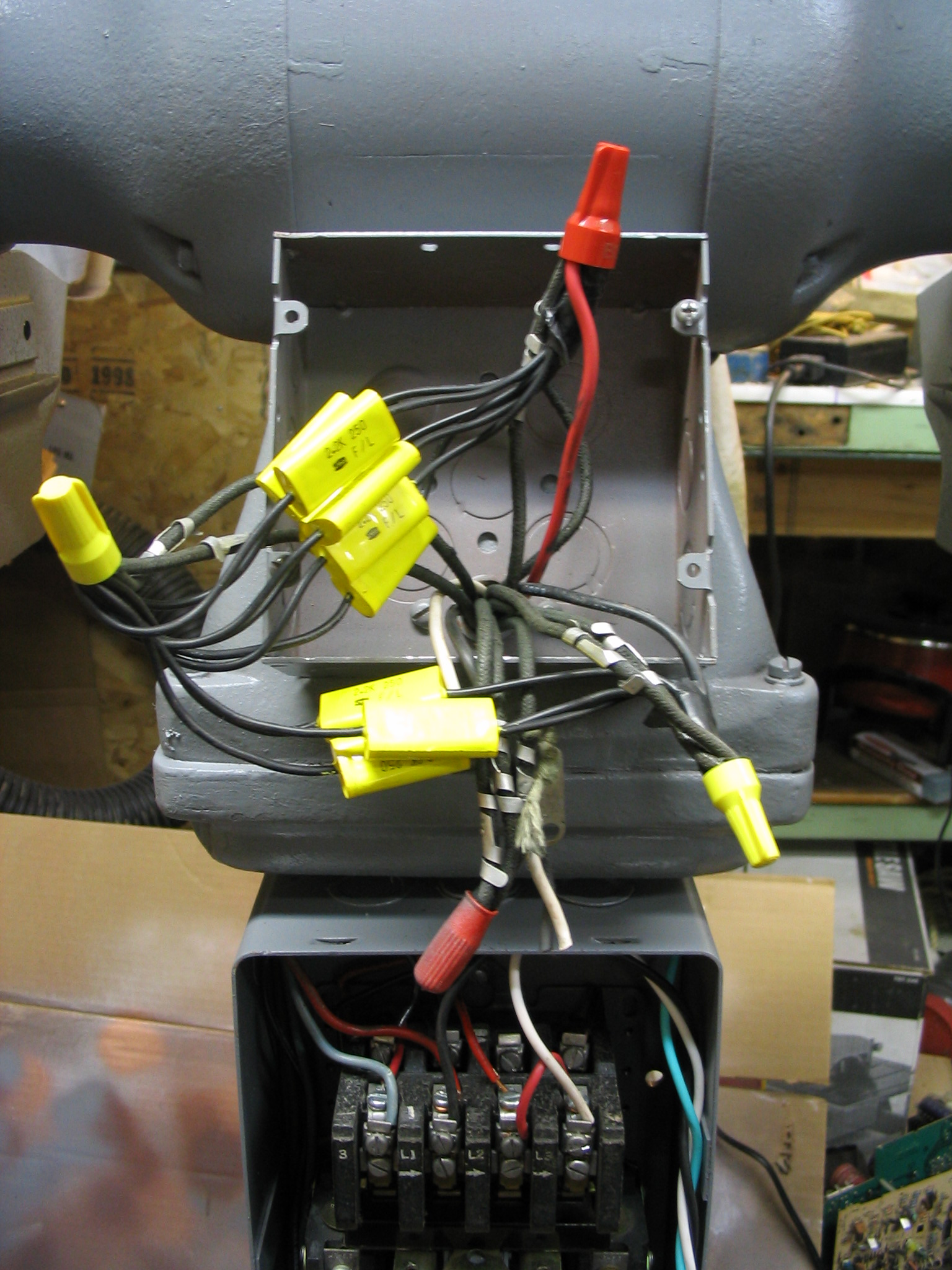
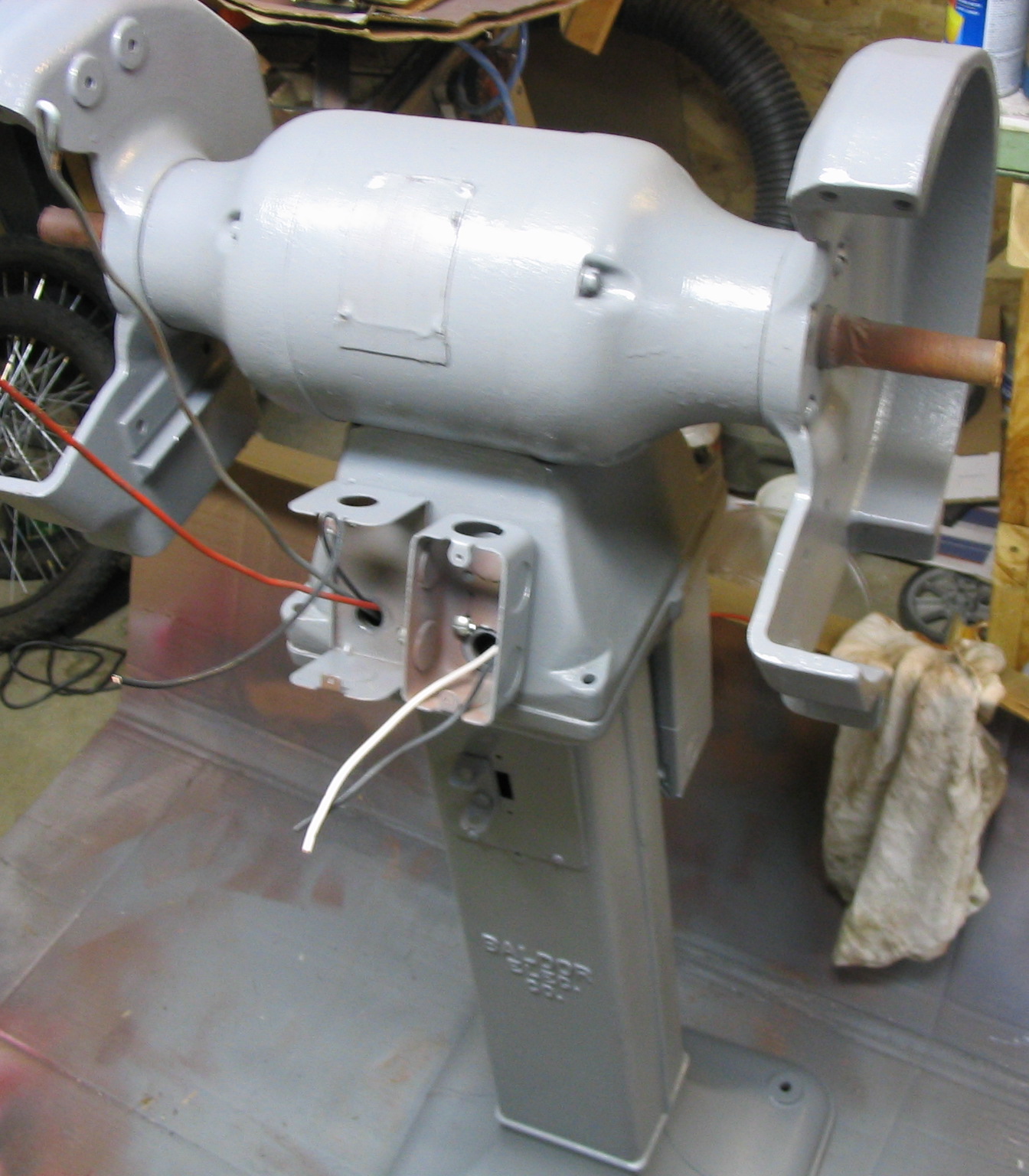
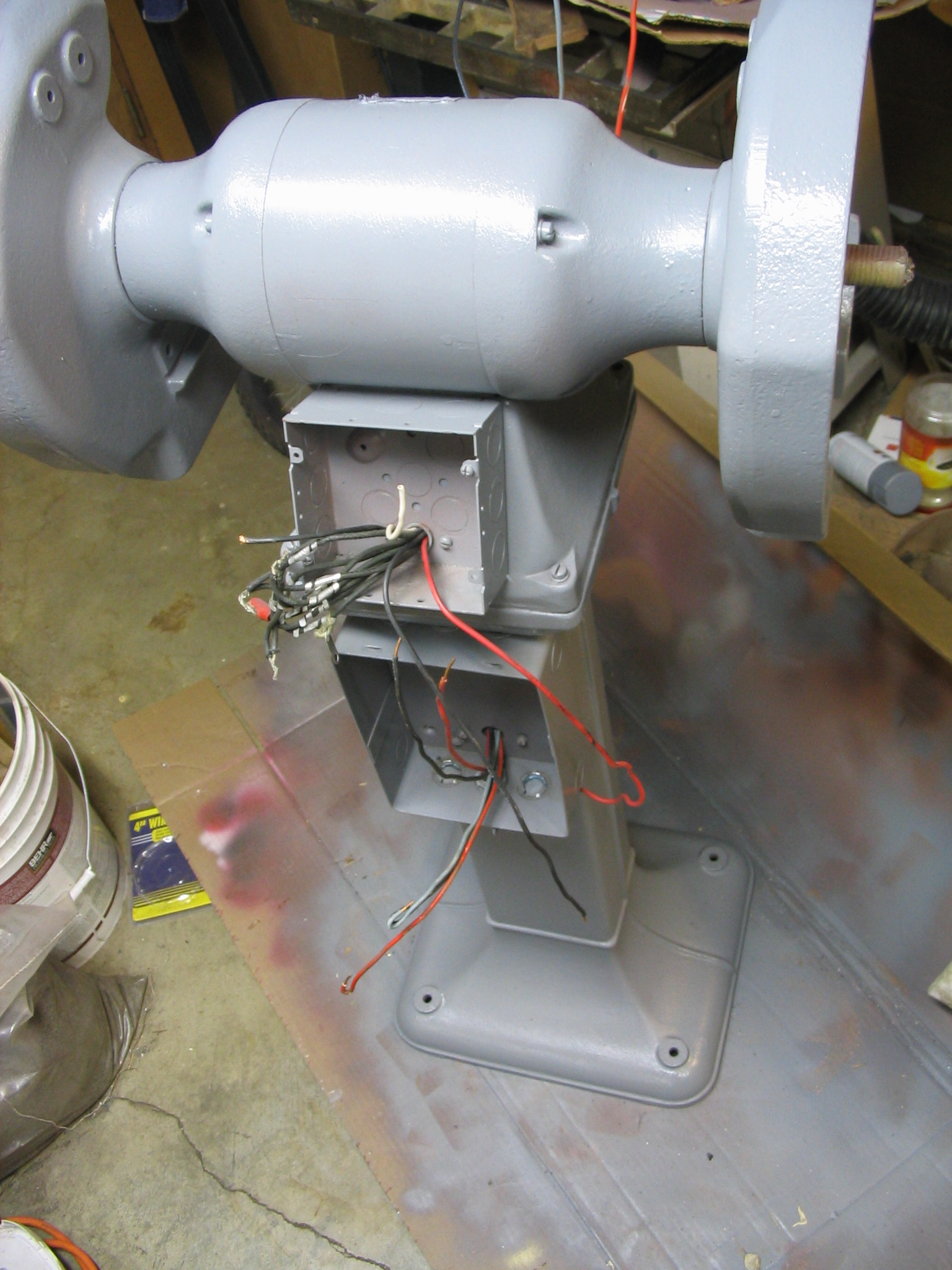
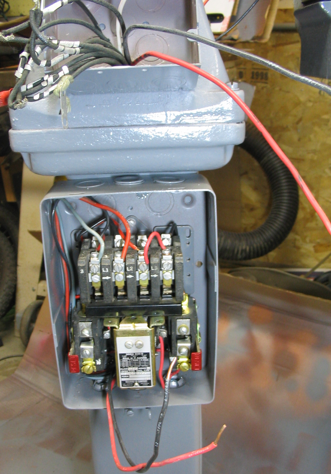
Construction
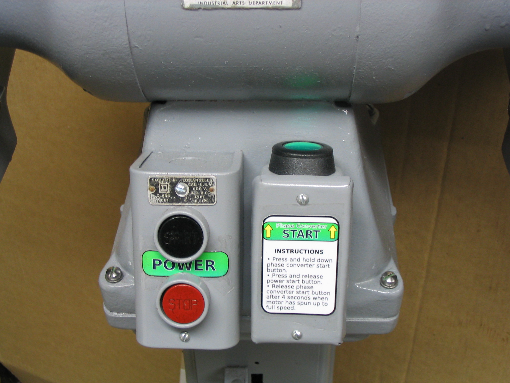
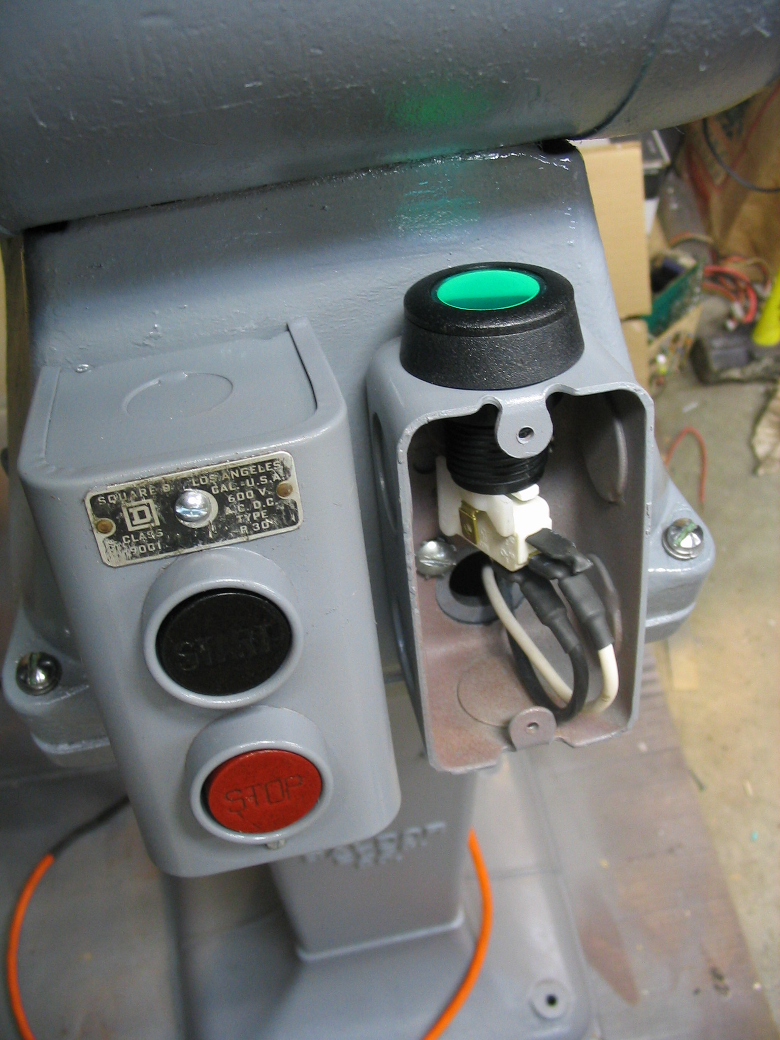
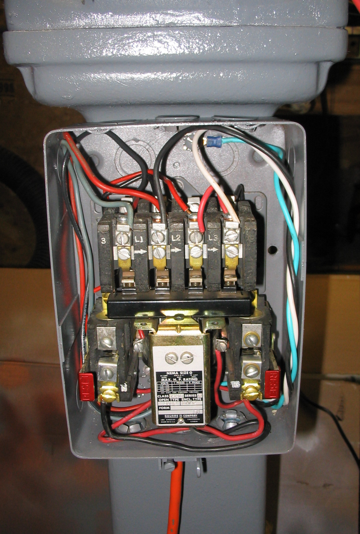
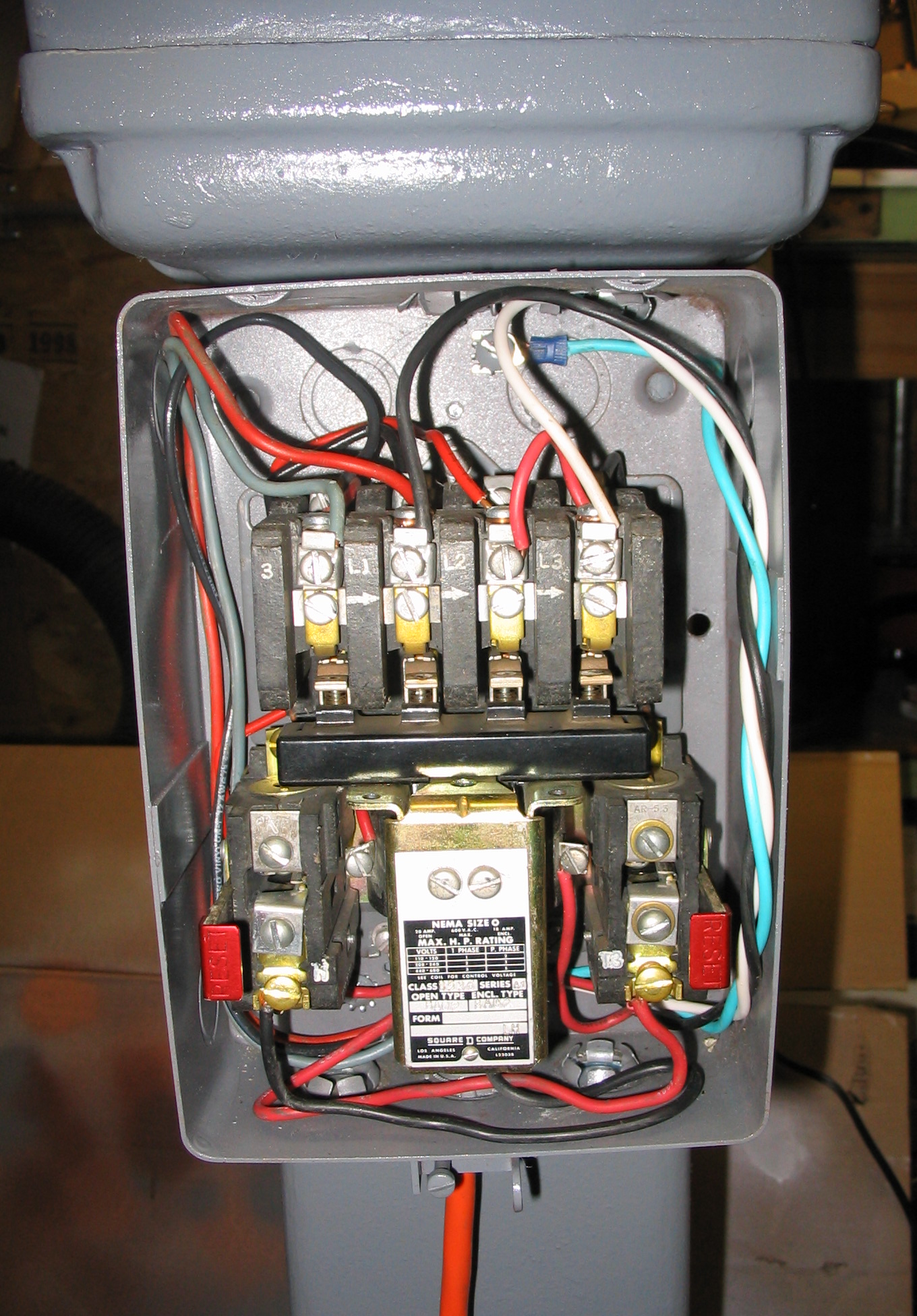
Figuring out the capacitor schematic and values was the hard part. The rest of the construction was relatively simple. The grinder already came with a large magnetic relay contact switch and circuit breaker, previously wall-mounted separately. I attached it to the back side of the pedestal stand, and put the push-button on/off switch on the front. I added two new electrical boxes: one on the front for the momentary start push button, and one on the back to hold the capacitors.
Since the voltage is double at 240v, I needed a different plug and outlet. But the amperage is low at 5 amps, so did not need a large super-heavy-duty power cord and plug like one might use with an electric clothes dryer or kitchen stove. I found a plug and outlet the same size as a standard US power plug, but with both prongs rotated at 90 degrees from standard, so neither side could be accidentally interchanged with a normal plug. Since the total amperage draw is only 5 amps, a 14-gauge power cord was adequate.
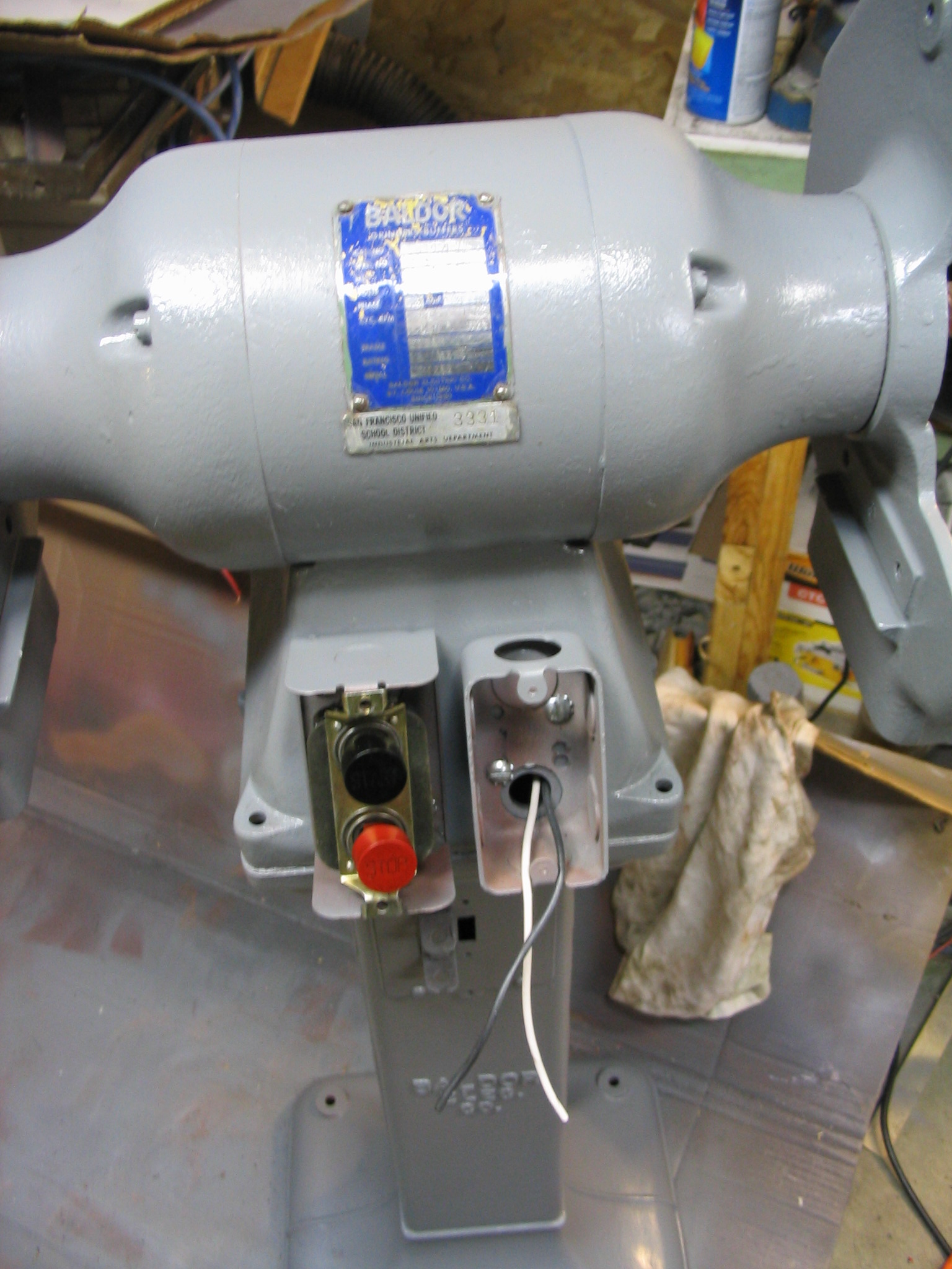
Result
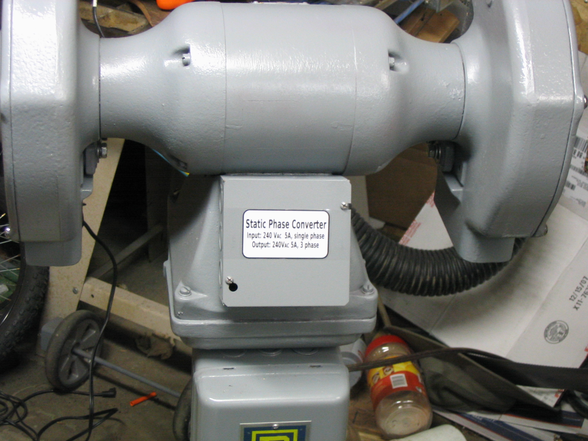 I created some labels using Inkscape, printed them on photo paper, and attached them to the various boxes.
The end result was very satisfying. The motor only takes about 4 seconds to spin up to speed, and the grinder works great.
Submitted by amillar on Tue, 2008-09-16 12:08
Hey Allan,
Thanks for this write-up! I just acquired a 3ph 1hp saw. Already bought a VFD for the thing, but I think I’ll try out the method you have listed here both to see if I can do it, and because it’ll open me up to the possibility of repeating the process, should another irrefusable 3ph/240v tool cross my horizon.
I have one question though (I did hunt around a bit before I’m asking this; I’m hoping you may have stumbled across the answer in your own research and simply didn’t think it relevant), though it comes in two parts:
1a. As I understand it, when a motor is first switched on, there is a “flood” or a “rush” of energy to satisfy its demands. A power spike. If the BSPC you describe needs to walk such a fine line of its input/output, why doesn’t this fry it?
1b. Any idea what happens if you DO exceed the expected boundary? I had a ShopVac once that would trip a breaker every time the filter got too clogged. Insufficient air intake, motor had to “work harder”, drew more current, POP! I mean, will it blow out the capacitors? Blow through the device hooked to the BSPC? Just blow UP?
Short answer: capacitors of this size, used with motors like this, are already designed to handle the currents needed.
This question is not really a fine line. In the BSPC, the capacitance in microfarads needs to be pretty specific to match your motor load. But the voltage and current ratings of the capacitors can be much higher than what you expect to need, with no downside. And they usually are.
Capacitors in these sizes are built for these kinds of motor power situations, so they are physically large to handle the current involved in motor start-up and run. Excess current in motor startup for motors like this only lasts for a few seconds.
If you really had capacitors that were undersized for current, they would overheat and burn out. They aren’t going to physically explode. You could possibly have some smoke, but most likely just burn out like a fuse. You keep stuff like this in a metal box, just in case of that.
If the capacitors burned out from overcurrent, then they simply would have no effect on the motor circuit, and the motor would act as if they weren’t there– it would hum and not rotate. Motor would stop running, but no fire or explosion.
Fortunately, I’ve seen no evidence of issues like any of this in the 10 years I’ve been using this one.