
Here is my crazy aviator costume from Halloween 2008. I was inspired by a recent steampunk ornithopter picture.
Tag: workshop
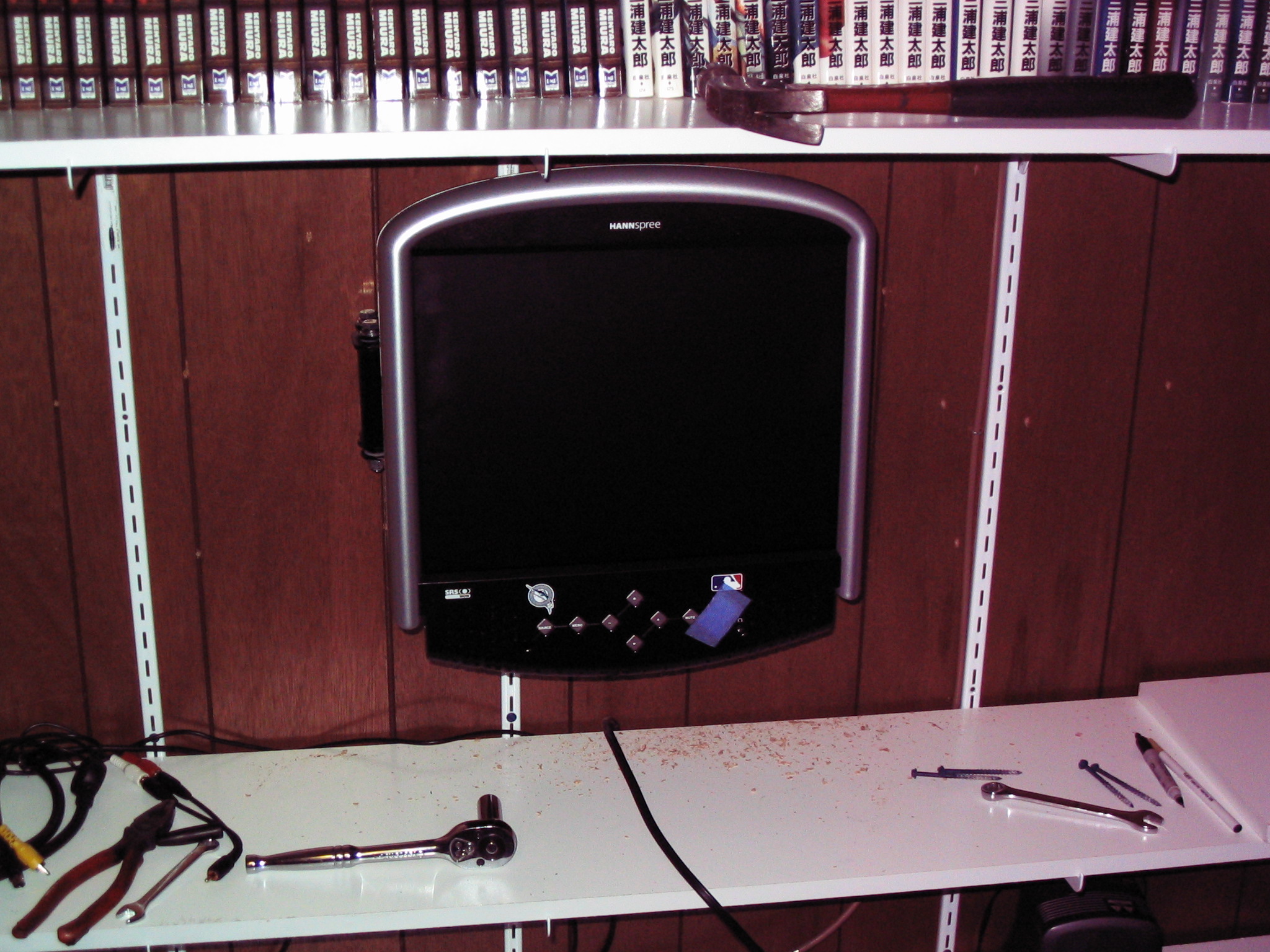
Flat panel TV swing-arm mount
 Jessica bought a flat panel TV, and wanted to attach it to the wall with some sort of swing-arm mount. The prices at the store were outrageous. Armed with my moderately-trustworthy arc welder and couple of discarded bed frames, we set out to construct one ourselves.
Mock-up
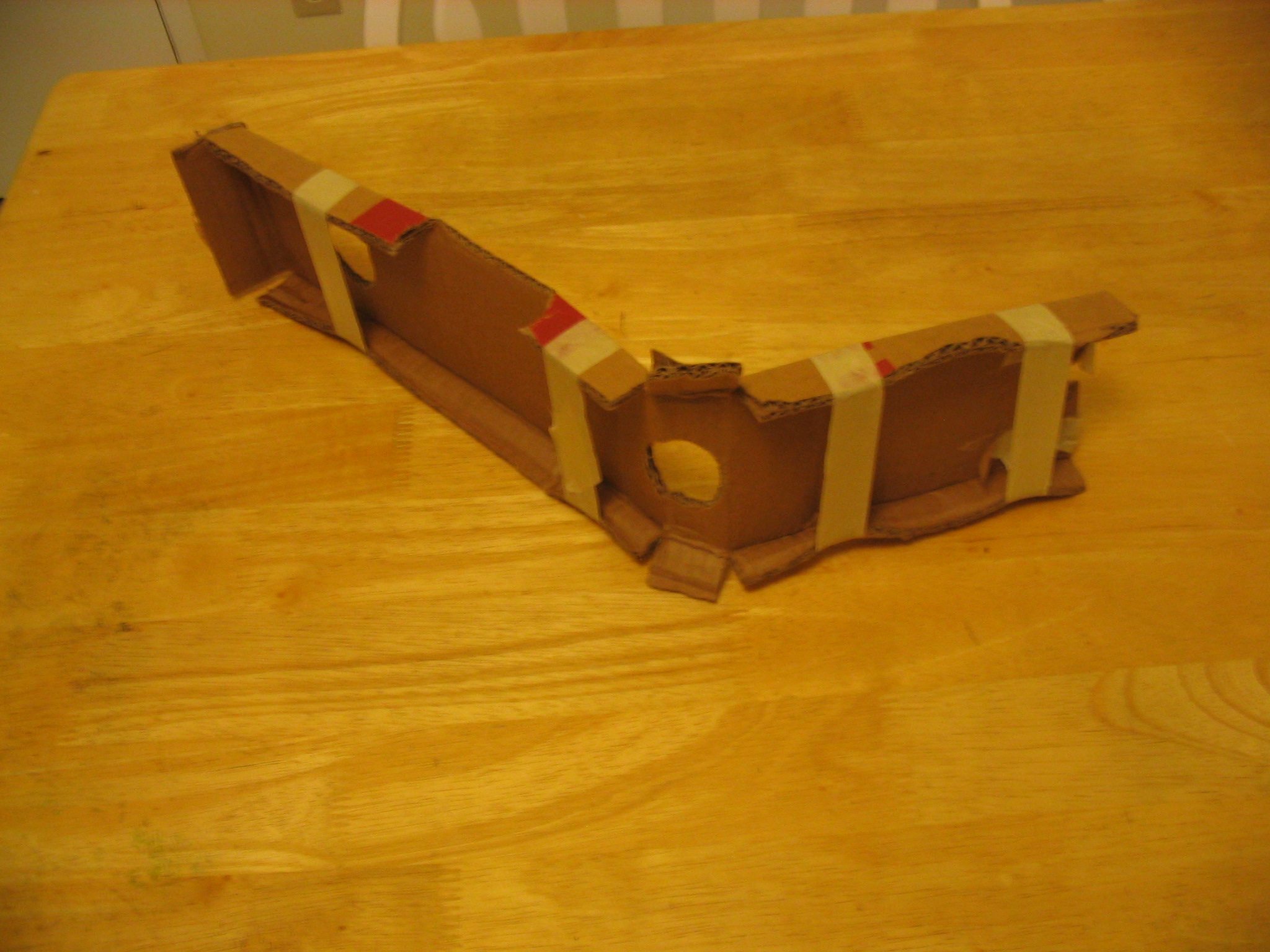
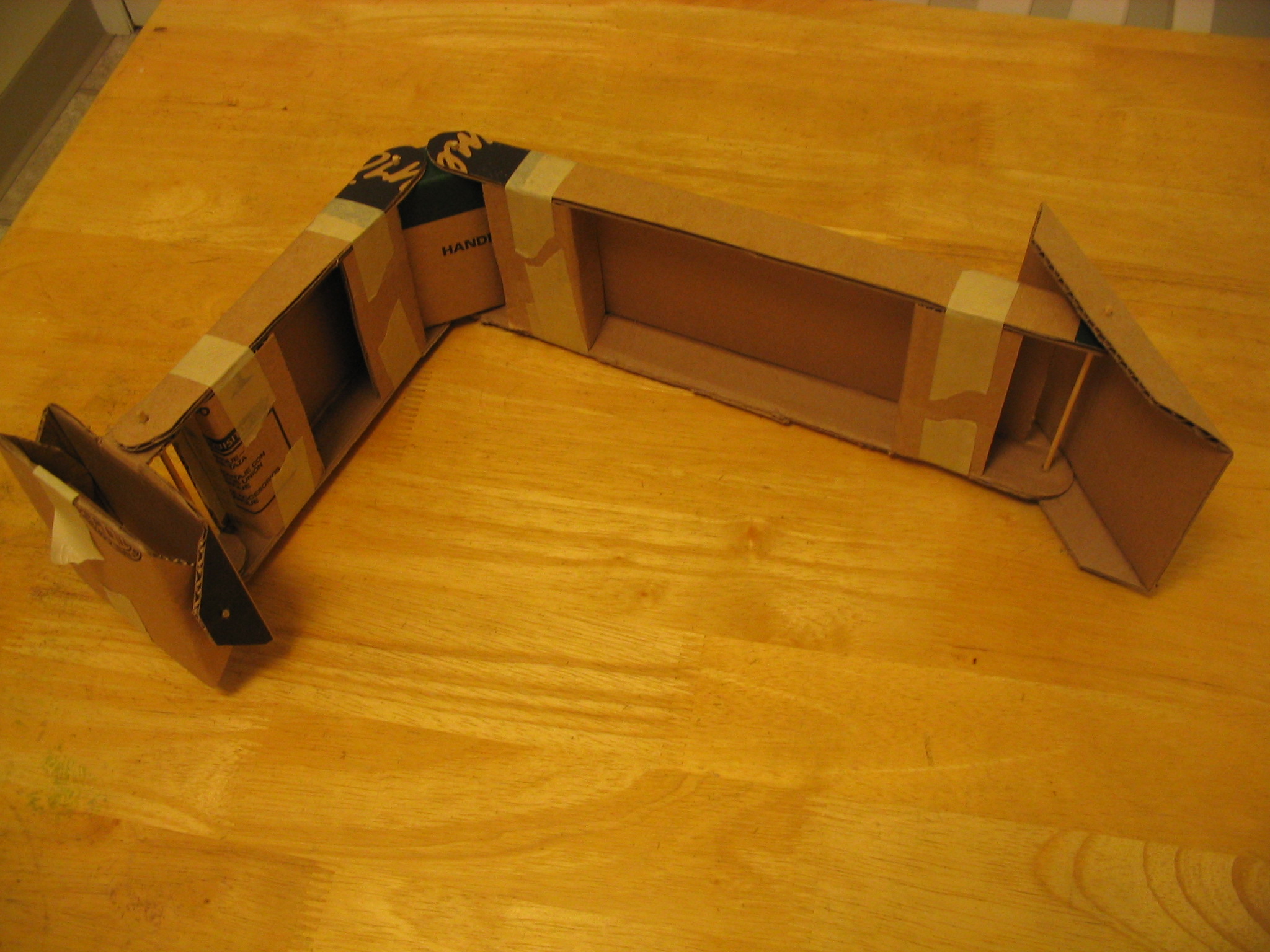
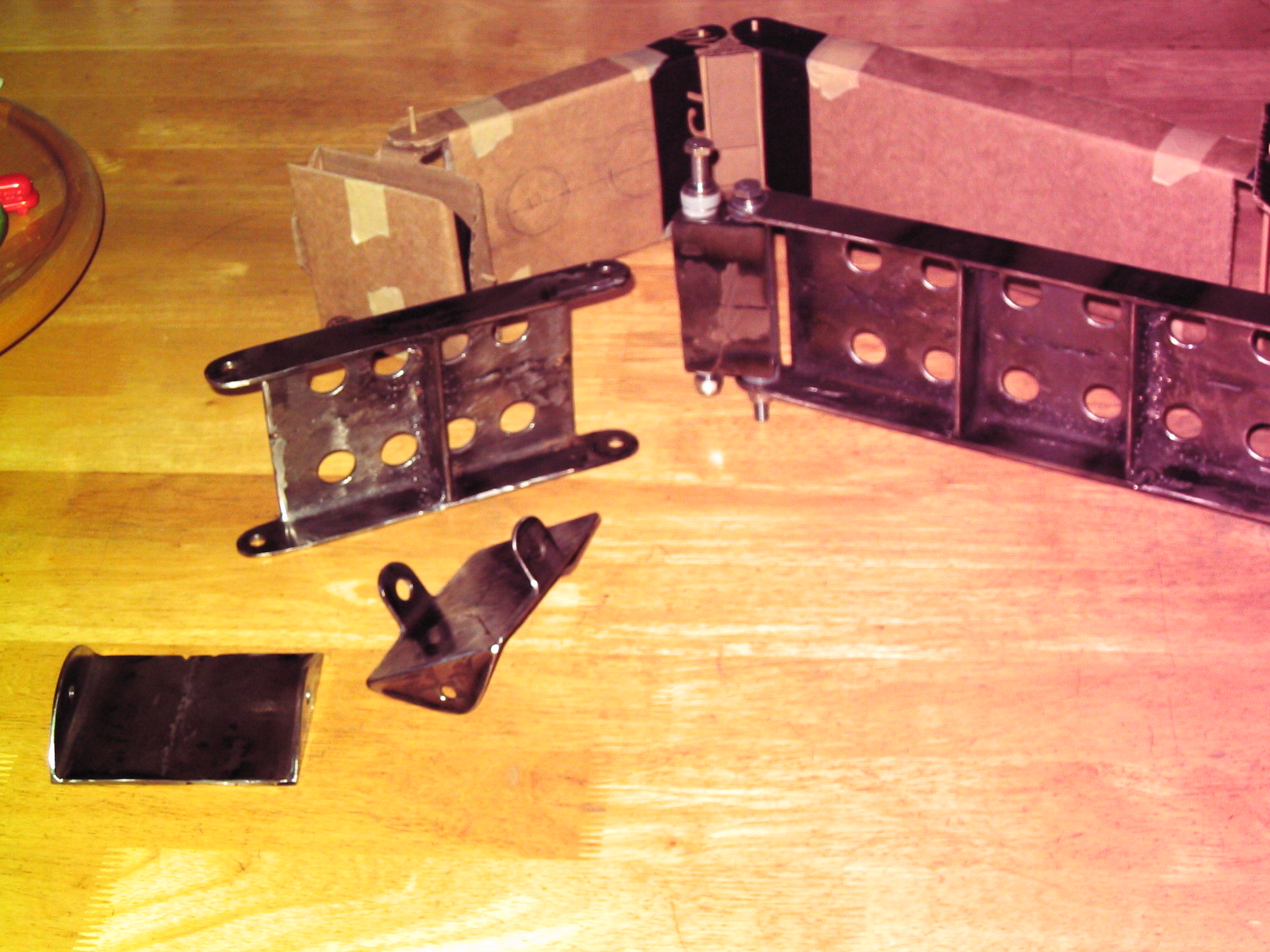
We started by building a cardboard mock-up model. We needed to determine the proper size and shape to fit the TV and wall. First we made a rough model by just bending the cardboard where we thought the joints should go. Then we made a second cardboard model which accurately fit the exact shape and size. We used bamboo skewers for the hinge pins. Once we had everything right, we were ready to build the real thing.
Construction
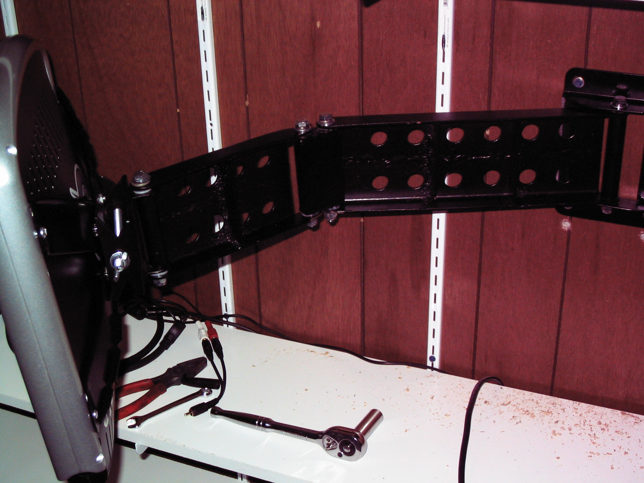
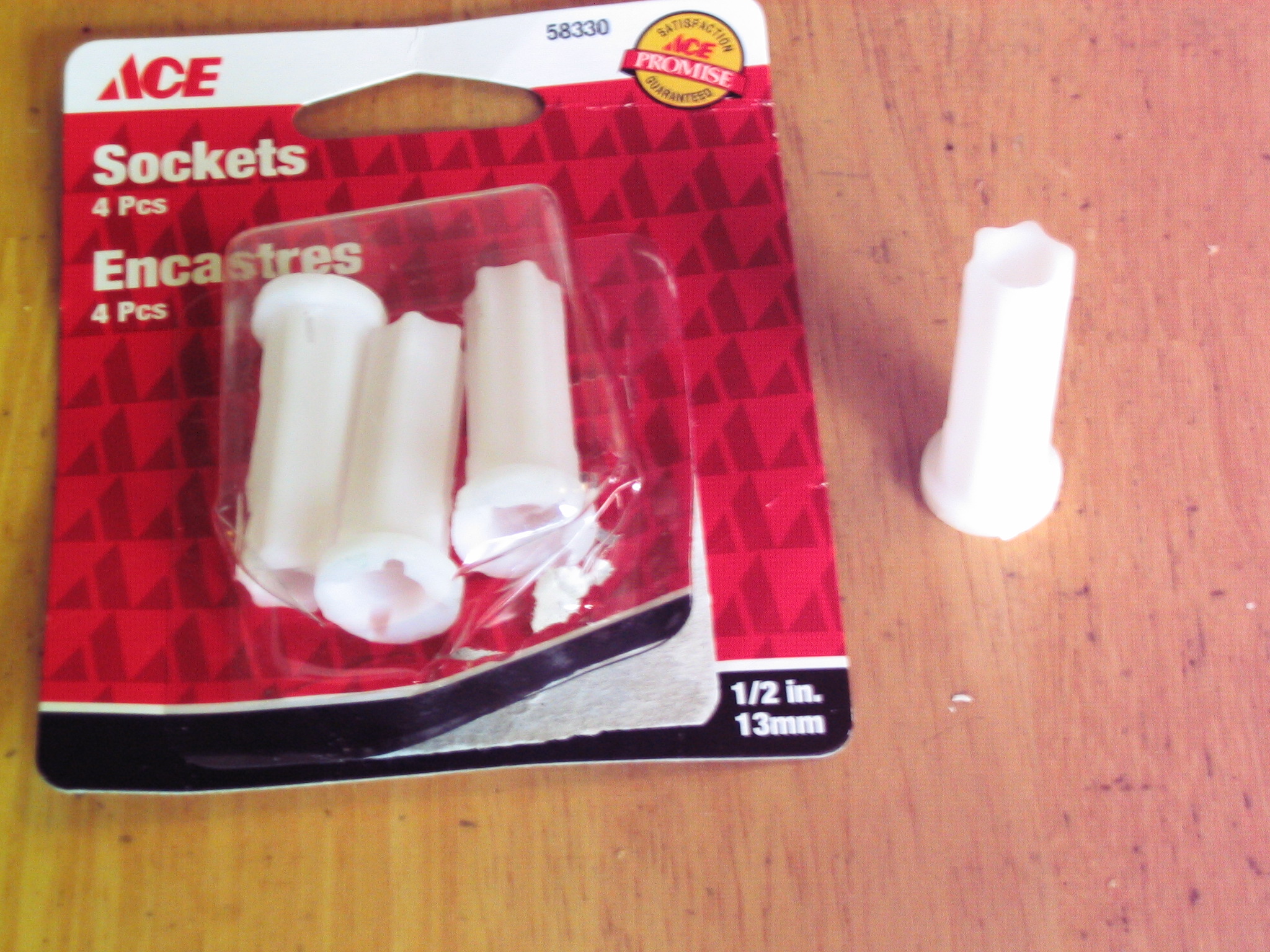
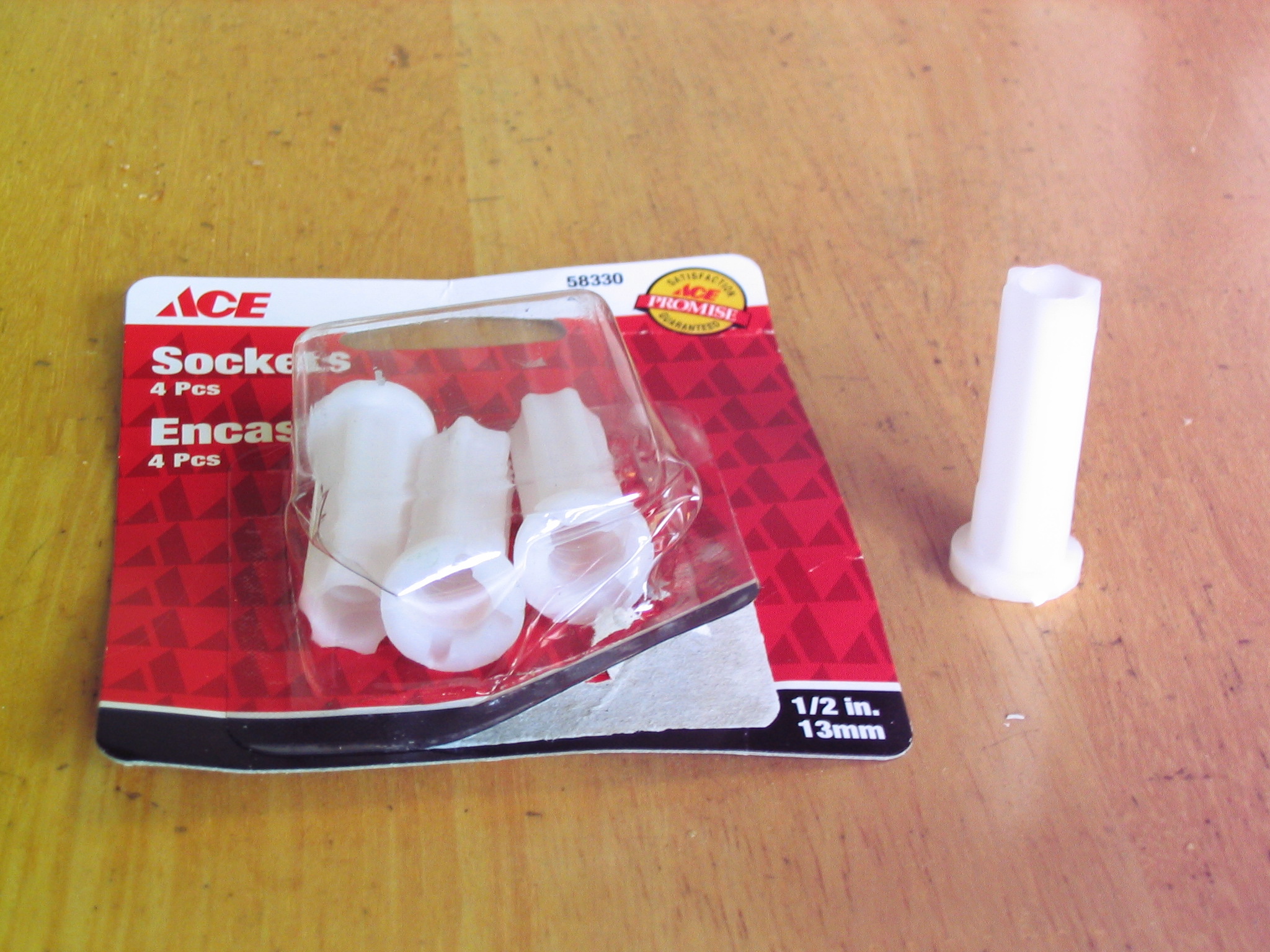
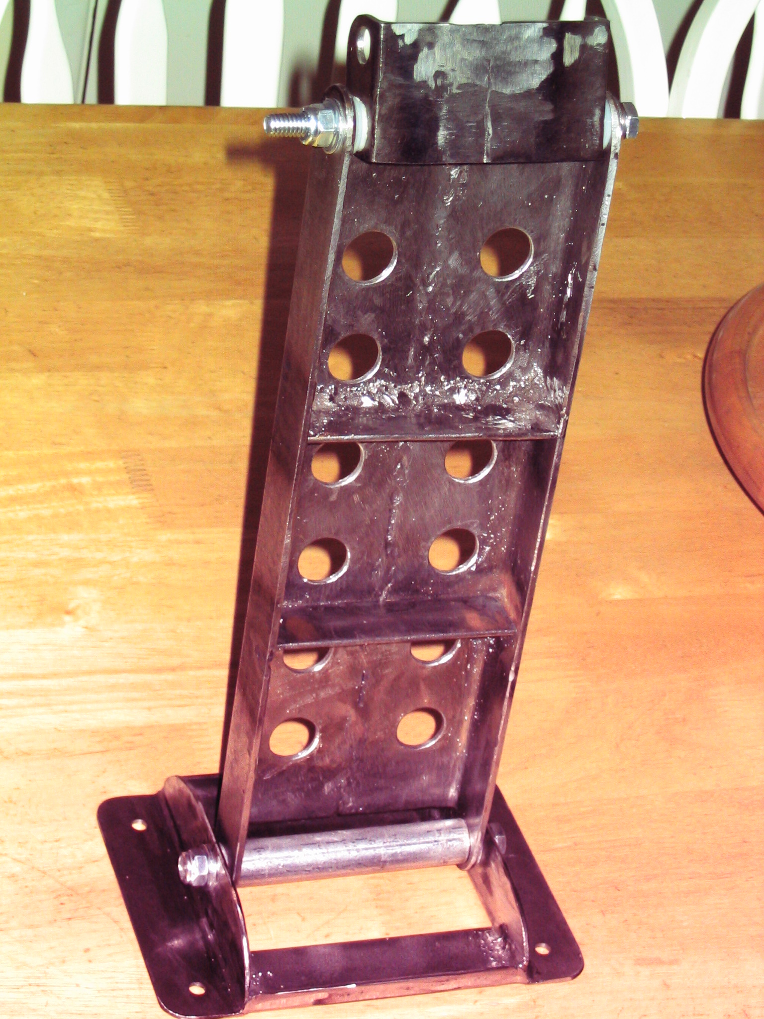
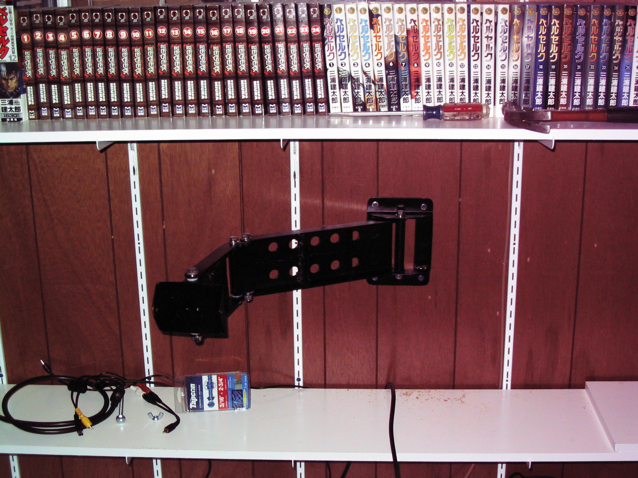
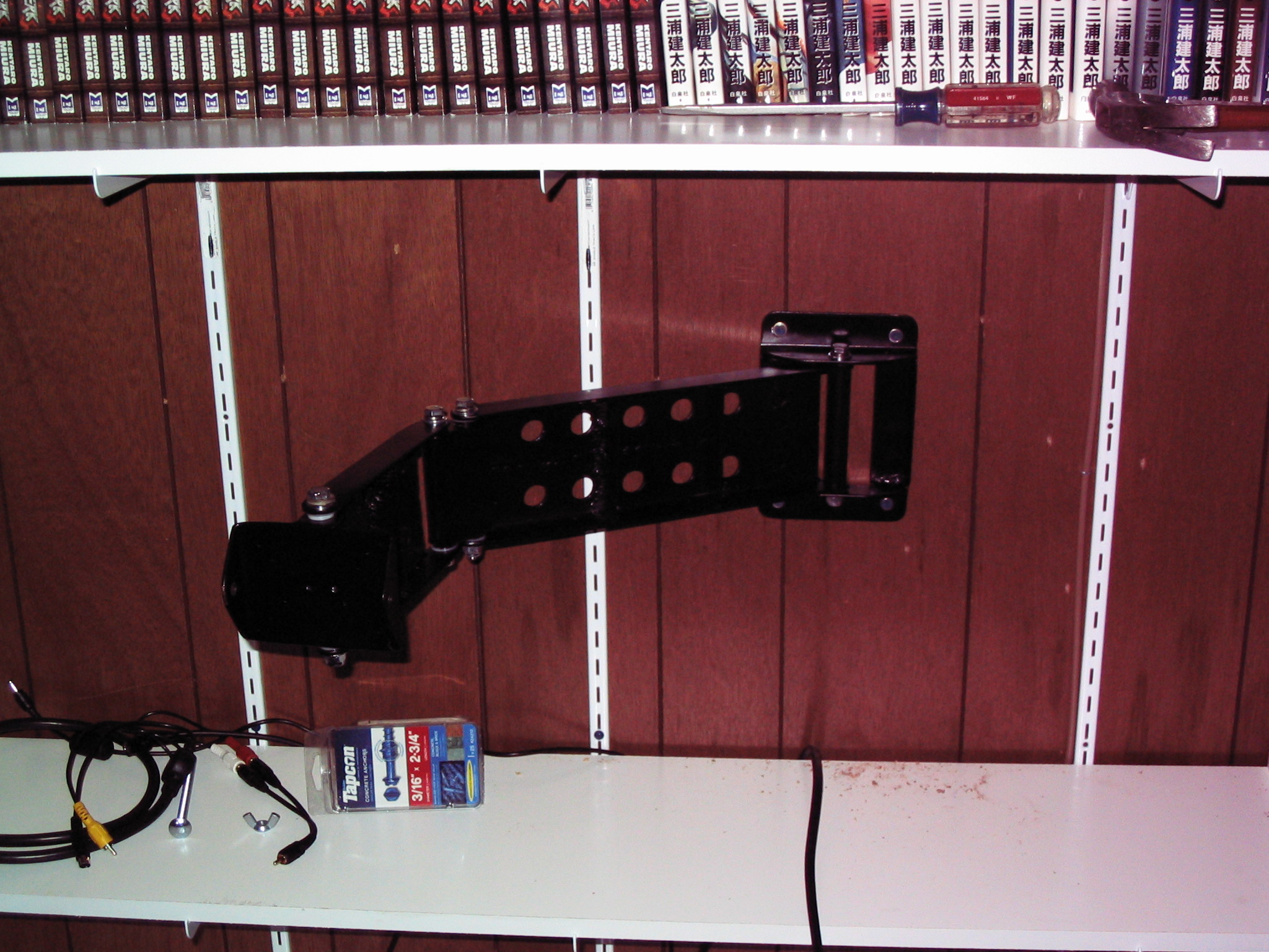
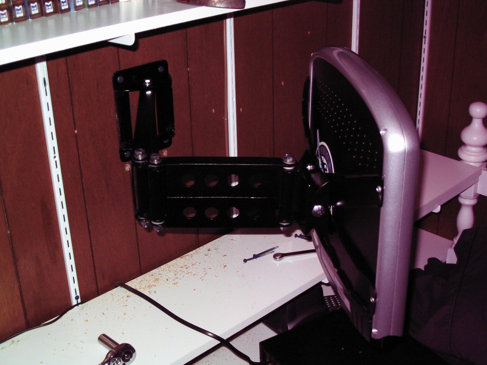
Construction mostly consisted of copying the cardboard pattern onto the angle iron. Most of the arm was fairly simple. The hinges were a challenge. I could not find nylon bushings at the hardware store to match the size of the bolts, so I used polyethylene sockets for caster wheels and trimmed them to fit.
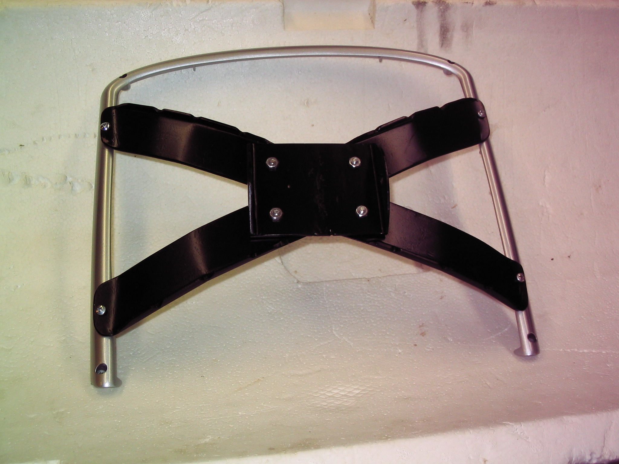
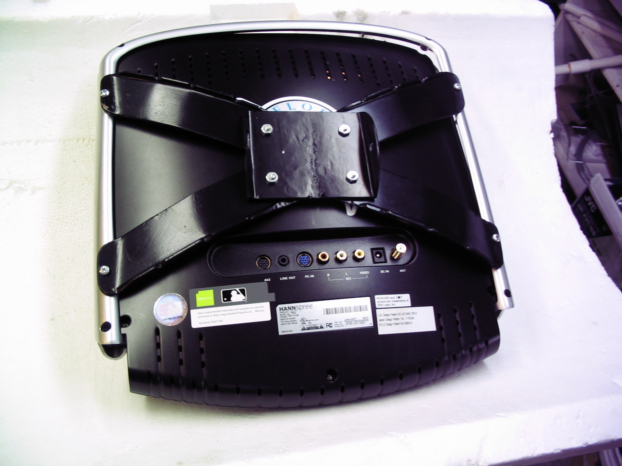
The TV was made to stand on a large foot; it did not include anything for a wall-mount bracket type of configuration. However, it was made with an aluminum frame around the perimeter. We removed the foot and made an X-shaped metal bracket, which we screwed to the frame at the outer edges.
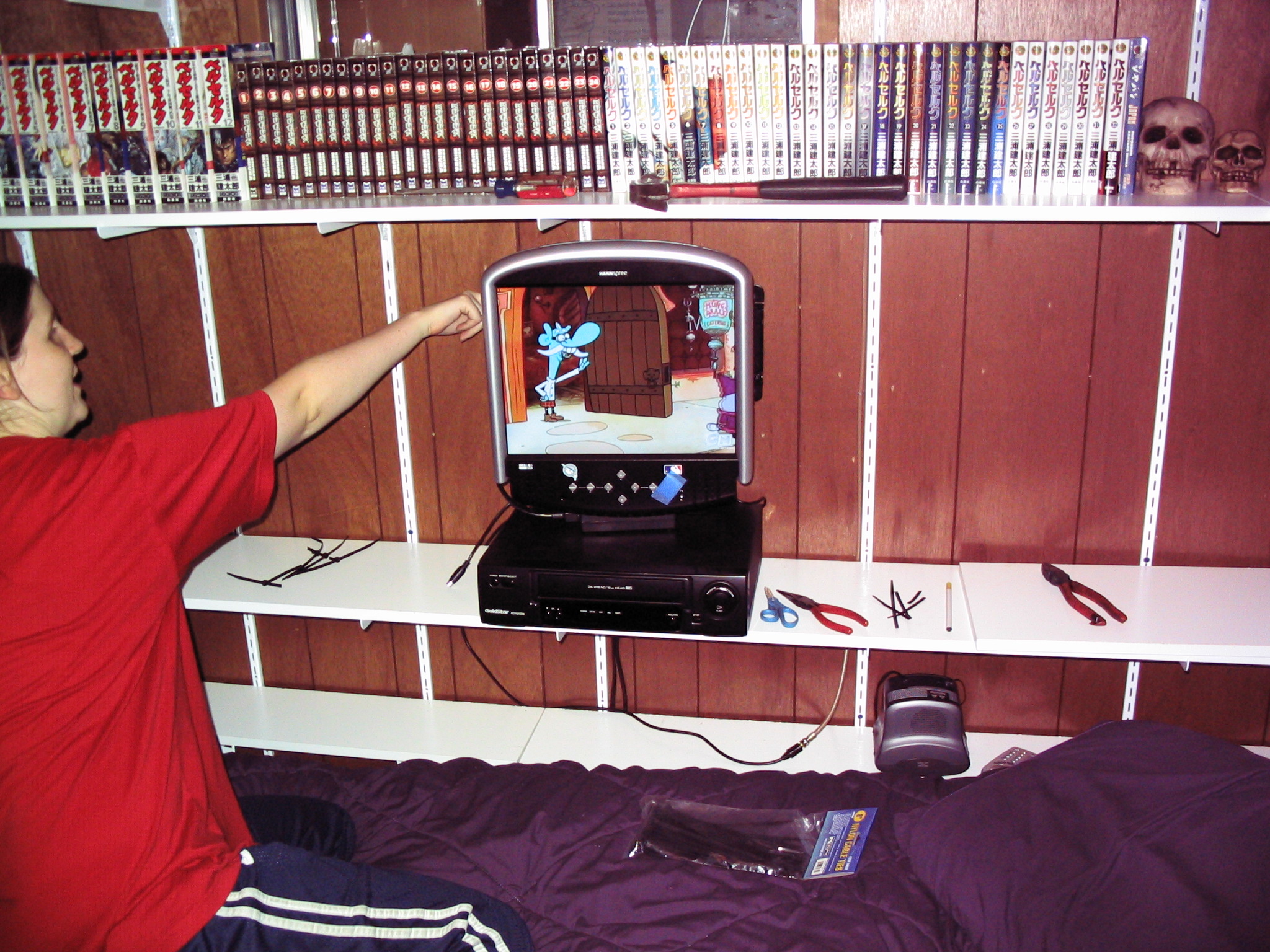
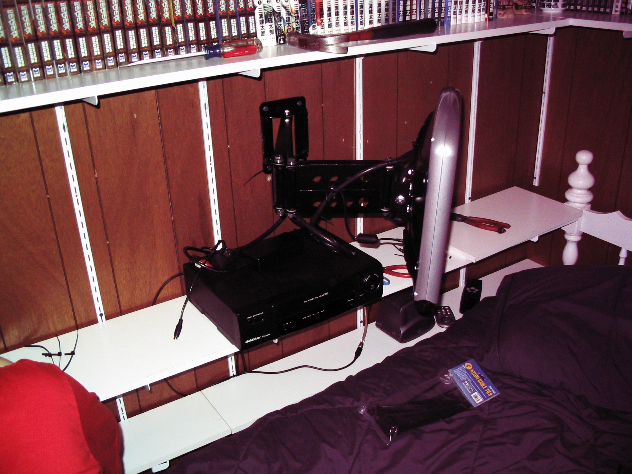
After the sections were welded and filed down smooth, we painted it black with semi-gloss spray paint. We bolted it to the wall with concrete anchors (since this wall is a solid concrete wall behind the panelling) and it works great.
Submitted by amillar on Sun, 2008-09-21 22:43
Baldor Grinder Restoration
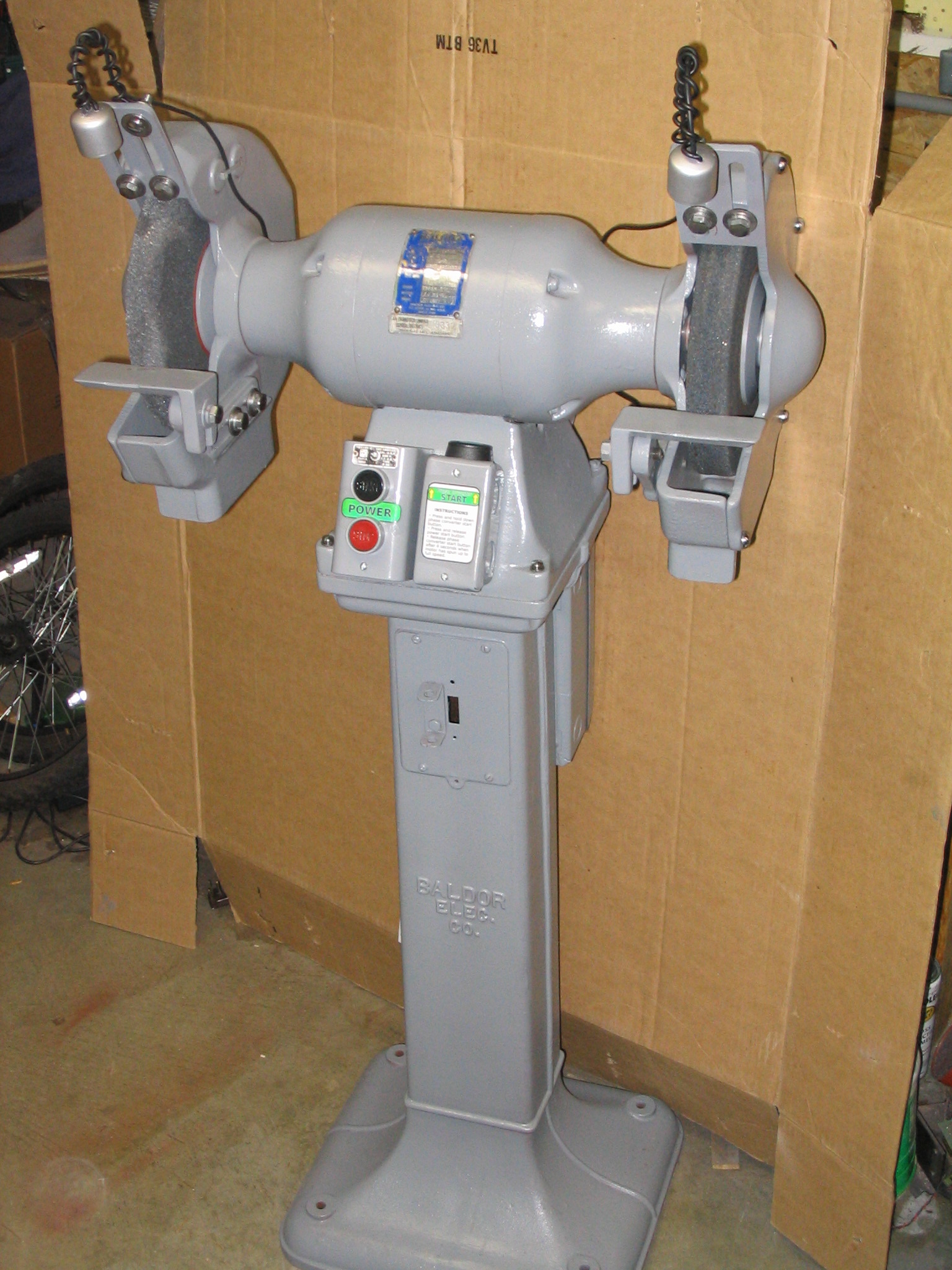
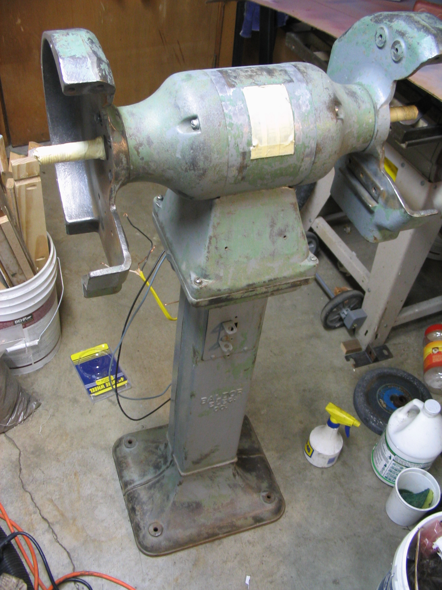
I received a Baldor metal grinder with 10-inch wheels, on its own pedestal floor stand, discarded from a school metal shop program. Several owners before me did not know what to do with it, mainly because the motor is wired for three-phase industrial power which is not found in U.S. residential homes. My job was to fix it up and get it working.
There were two major tasks to the restoration: cleaning/repainting, and making the three-phase motor work.
Cleaning and Painting
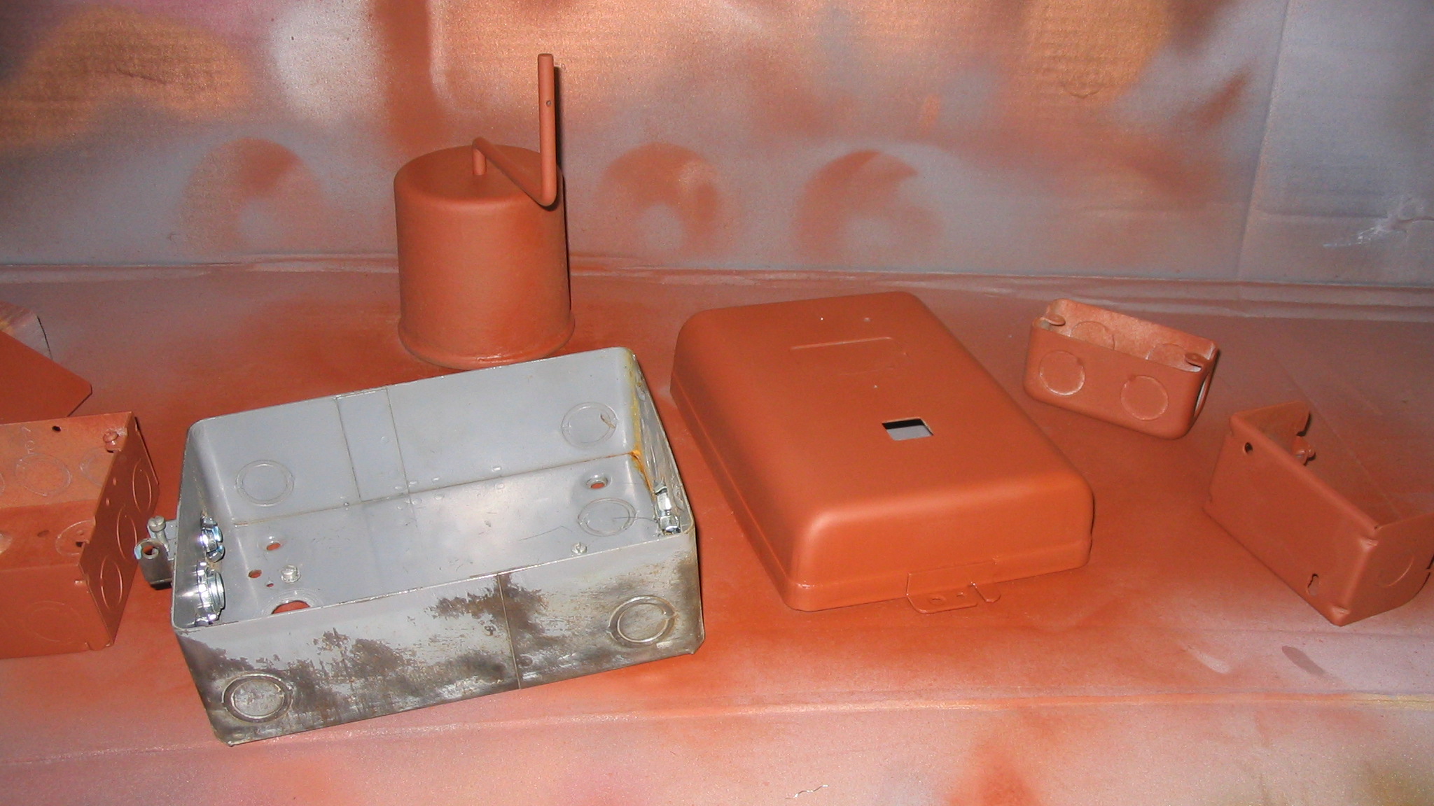
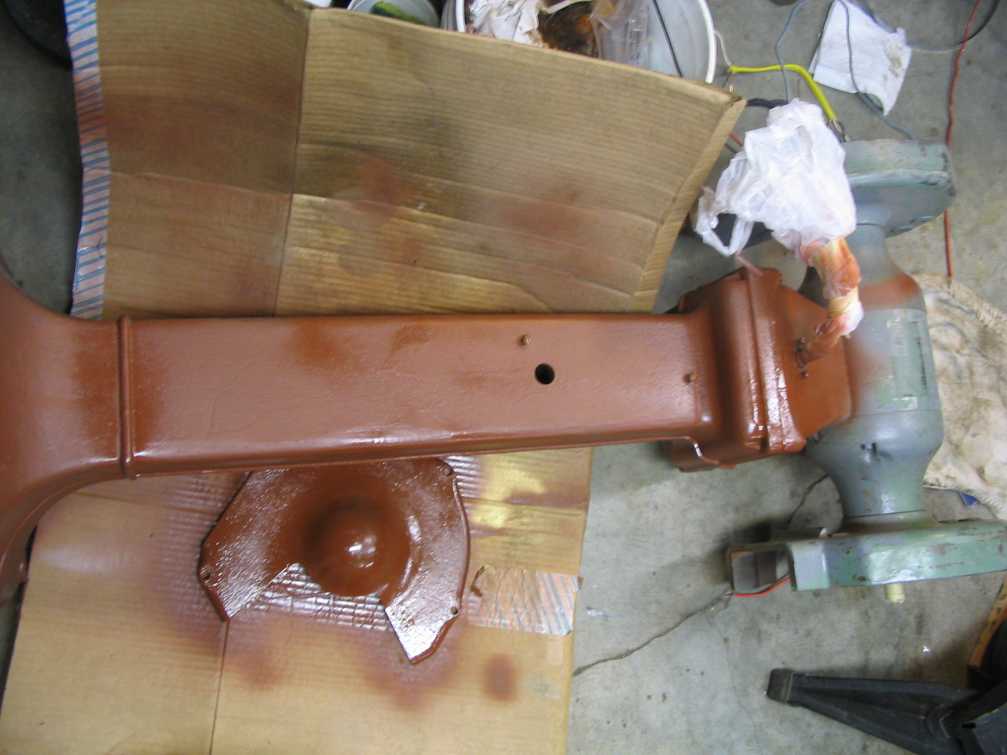
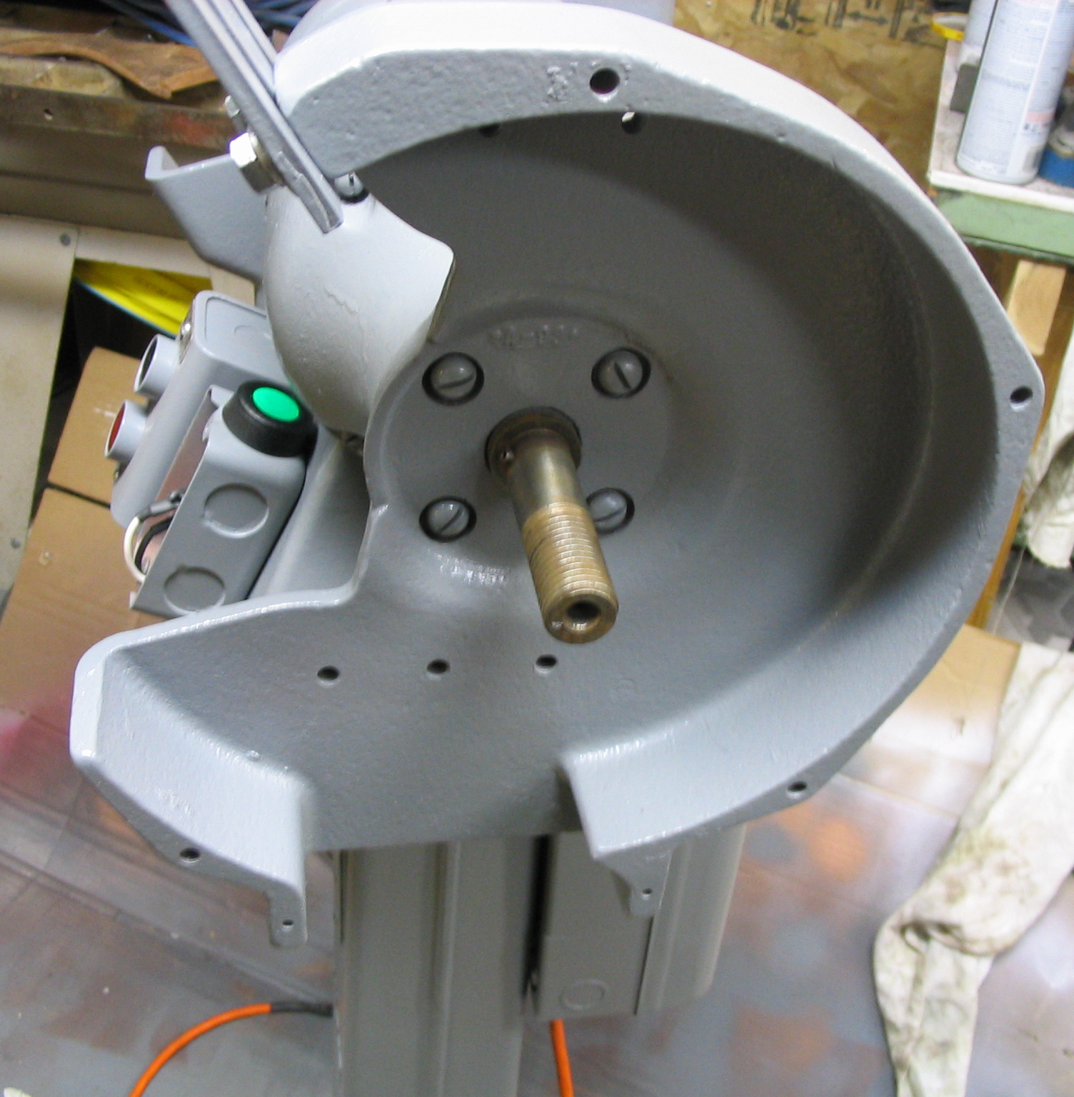
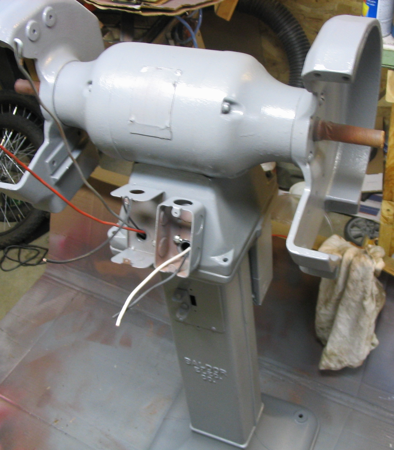
I started the cleaning process by removing all attachments that I could, including the wheel shroud side covers, the wheels themselves, and all electrical boxes and covers. I remove all of the old flaking paint and minor rust spots using a wire wheel brush on the electric drill. Some of the paint was still good, but much of it was stripped down to the bare metal. I could not remove the riveted-on motor label and didn’t want to paint the wheel axles, so I covered them with masking tape.
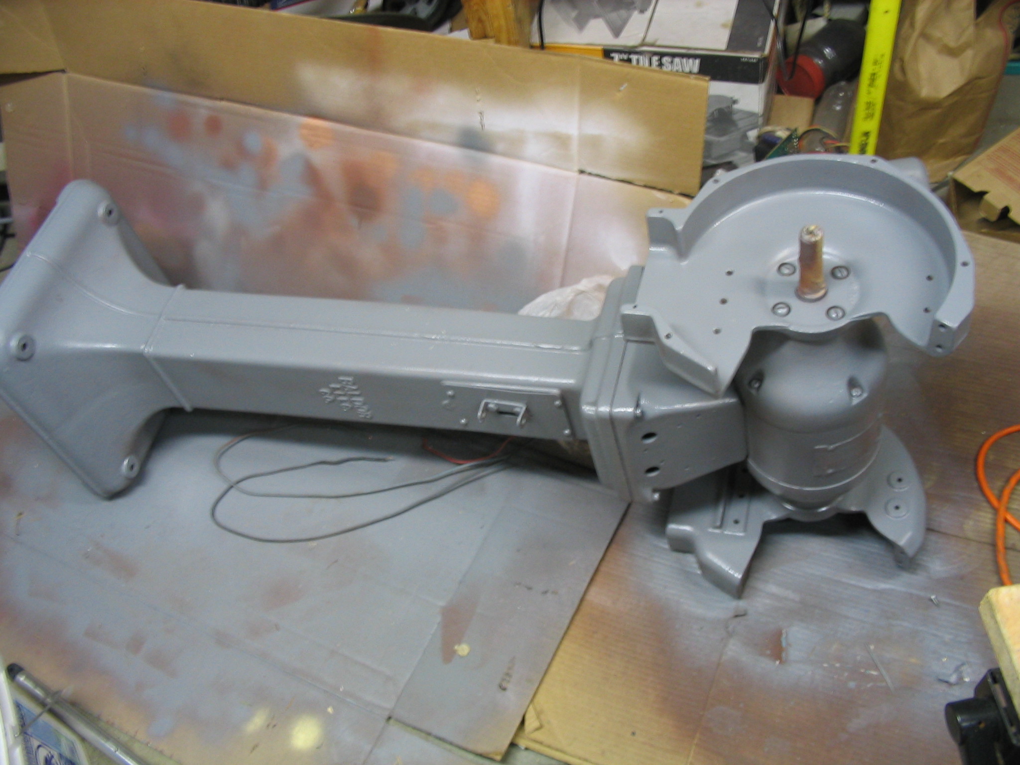
I spray painted the entire grinder and all the separate parts with primer for a good base coat. I followed it with a few coats of grey paint.
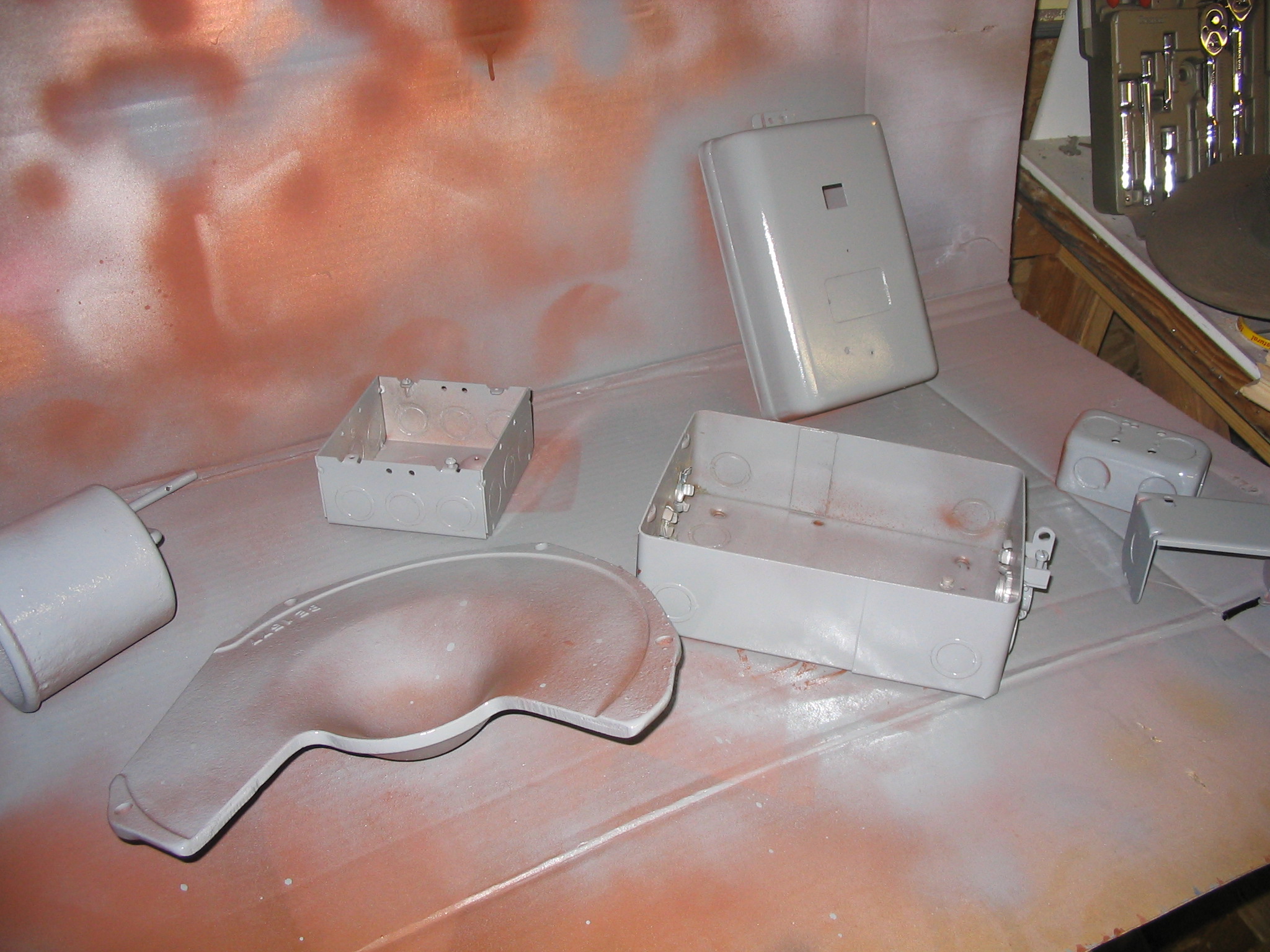
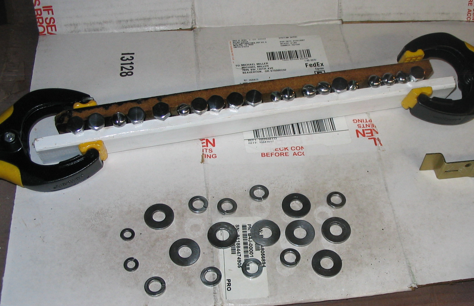
I cleaned up the hardware to make it look a little nicer. I filed and sanded the heads of the screws and bolts while spinning them in the drill press. I buffed all of them with a cloth wheel, which made them nice and shiny. I finished it with some clear spray varnish.
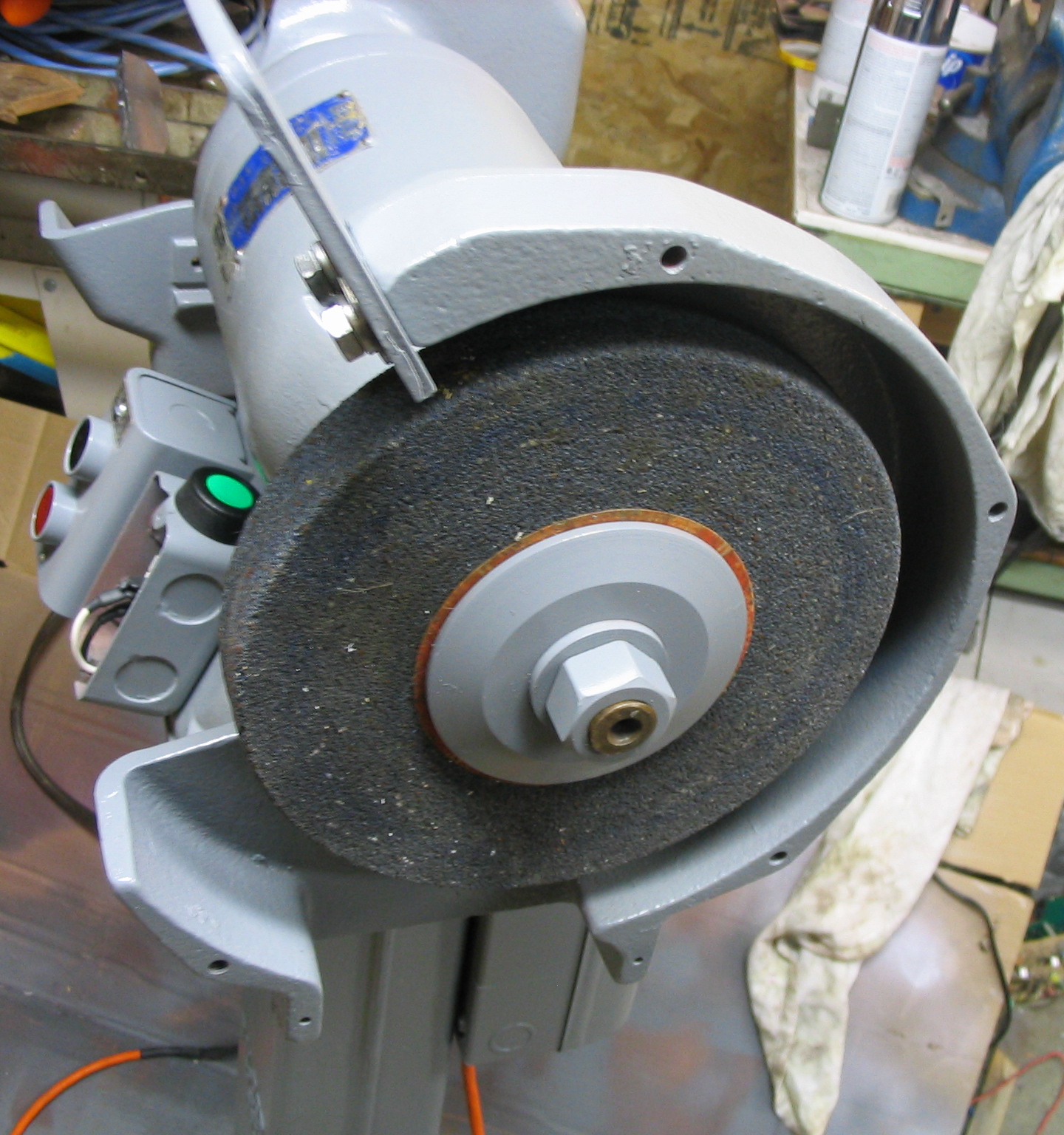
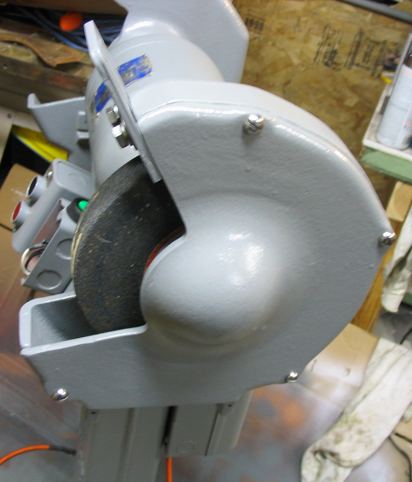
I reassembled all the pieces, back in the order they came off.
Electrical
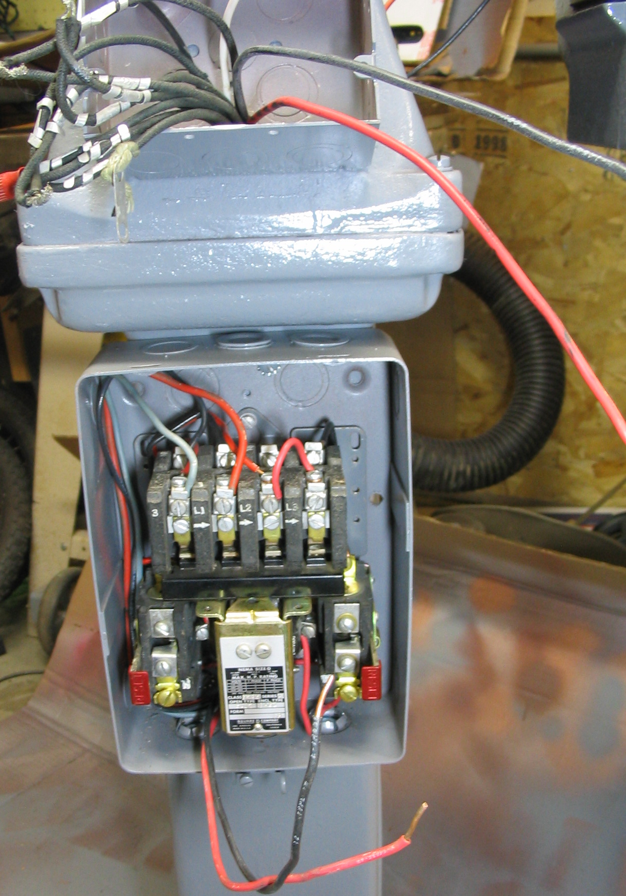
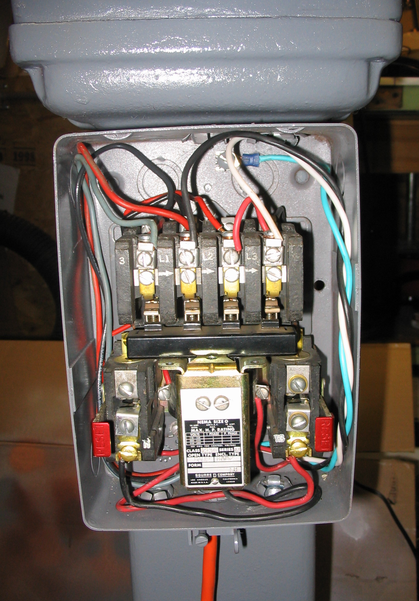
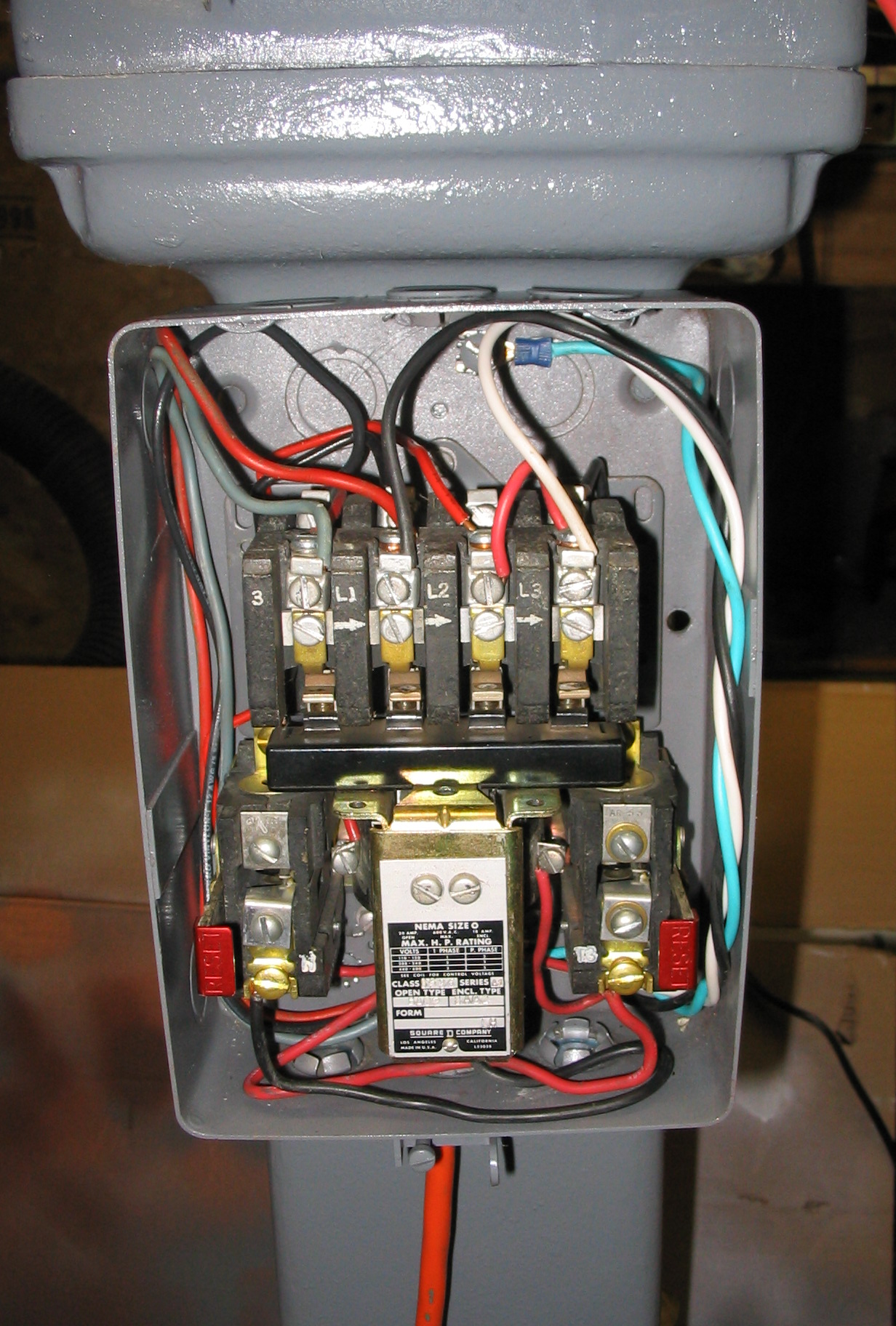
Originally this grinder was hard-wired to the wall using “BX”-style flex conduit. There was a power relay and circuit breaker box, which engaged and disconnected all three phases in sync, using start and stop push buttons.
For the 3-phase power, I built a
static phase converter using capacitors.
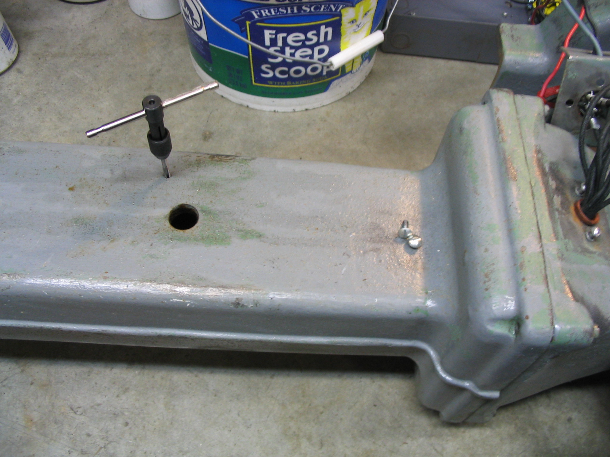
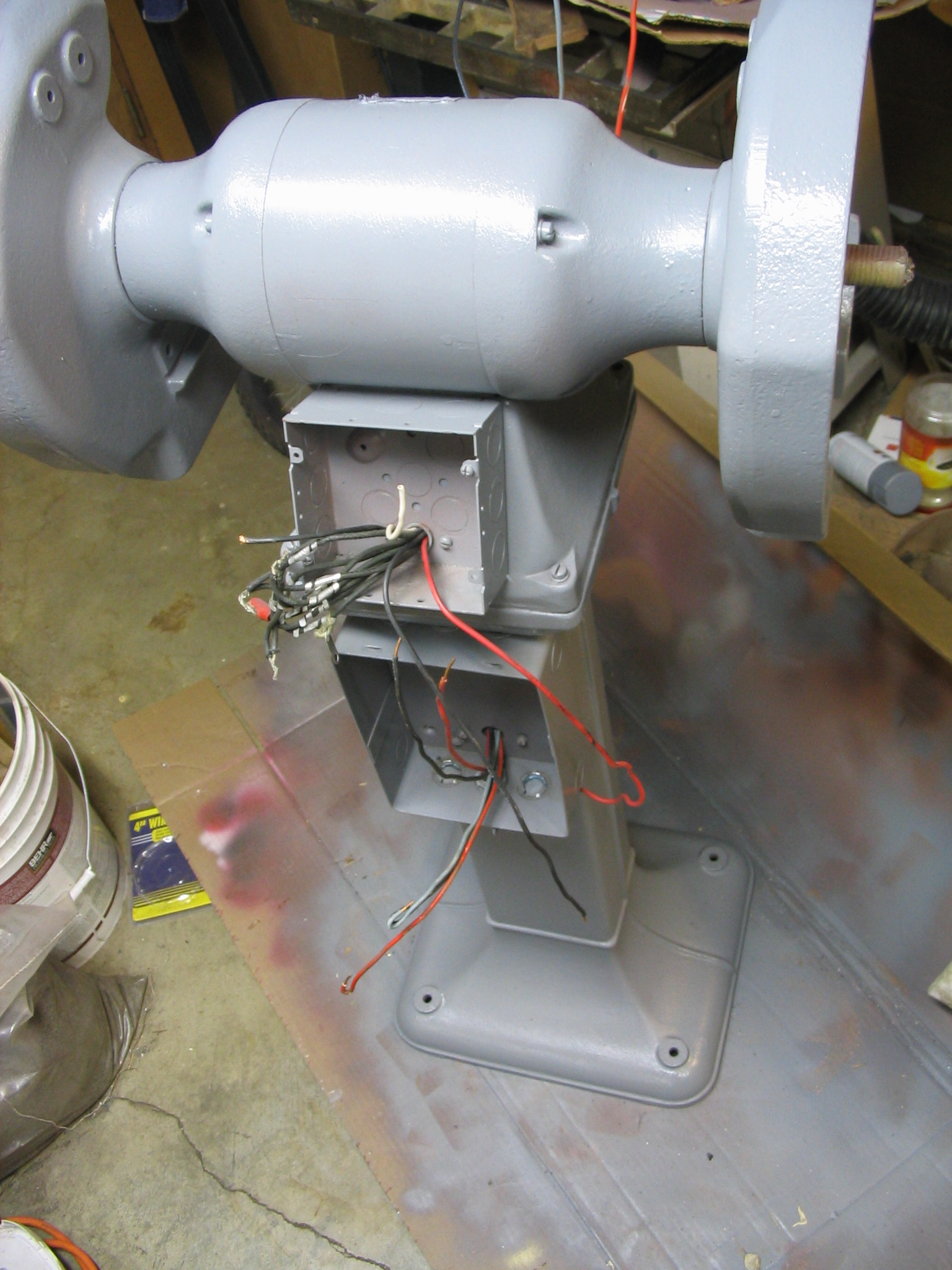
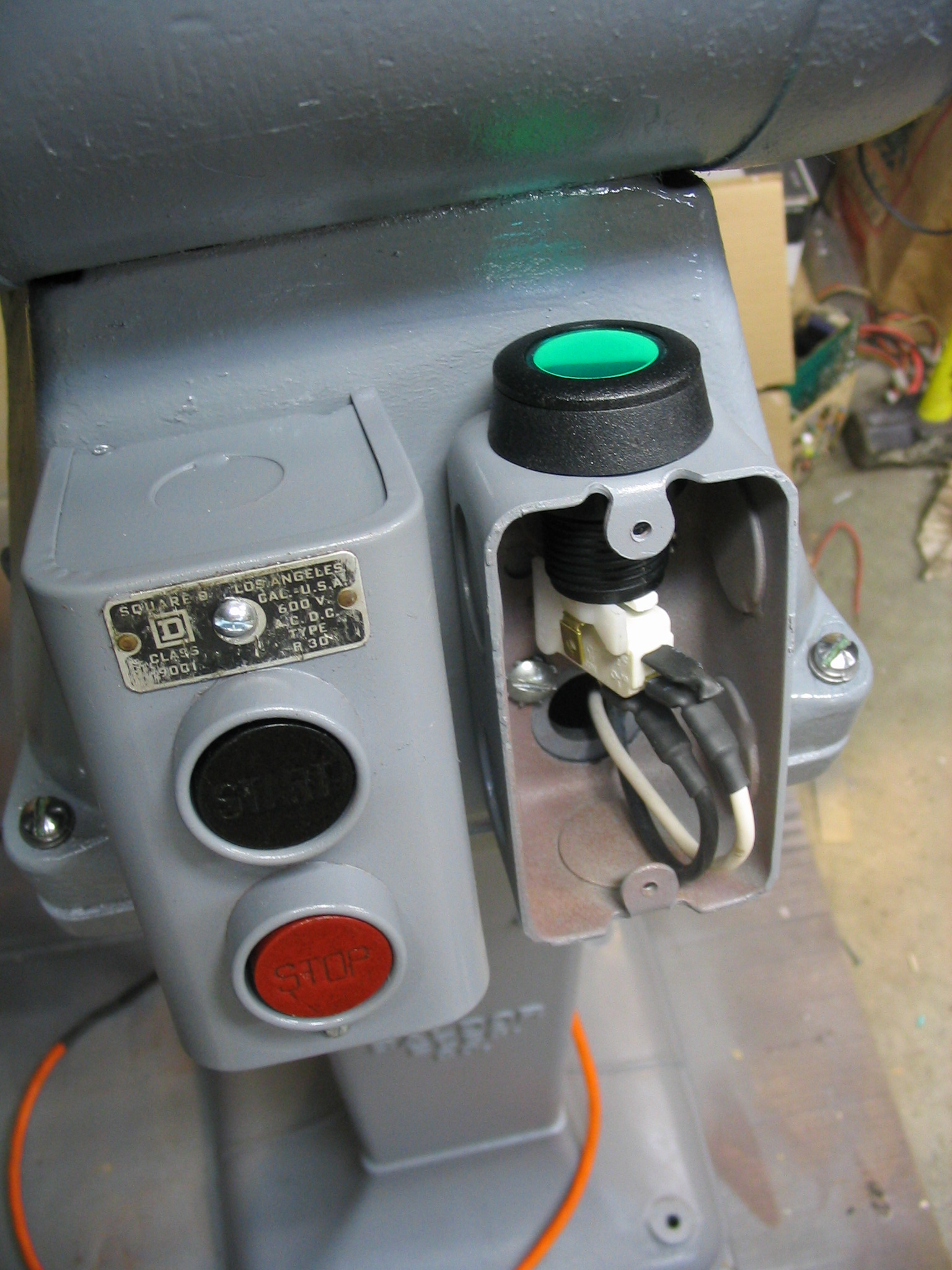
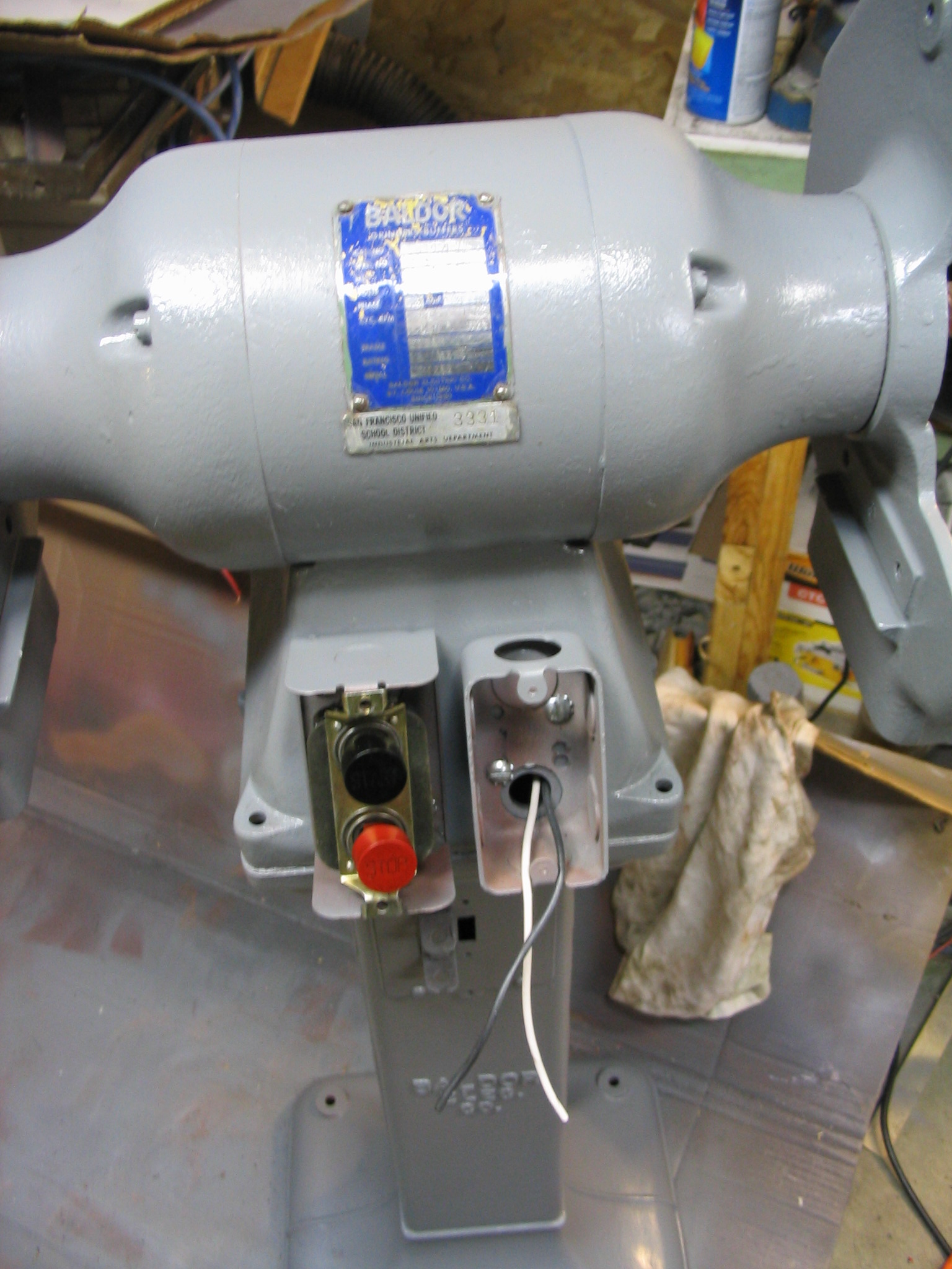
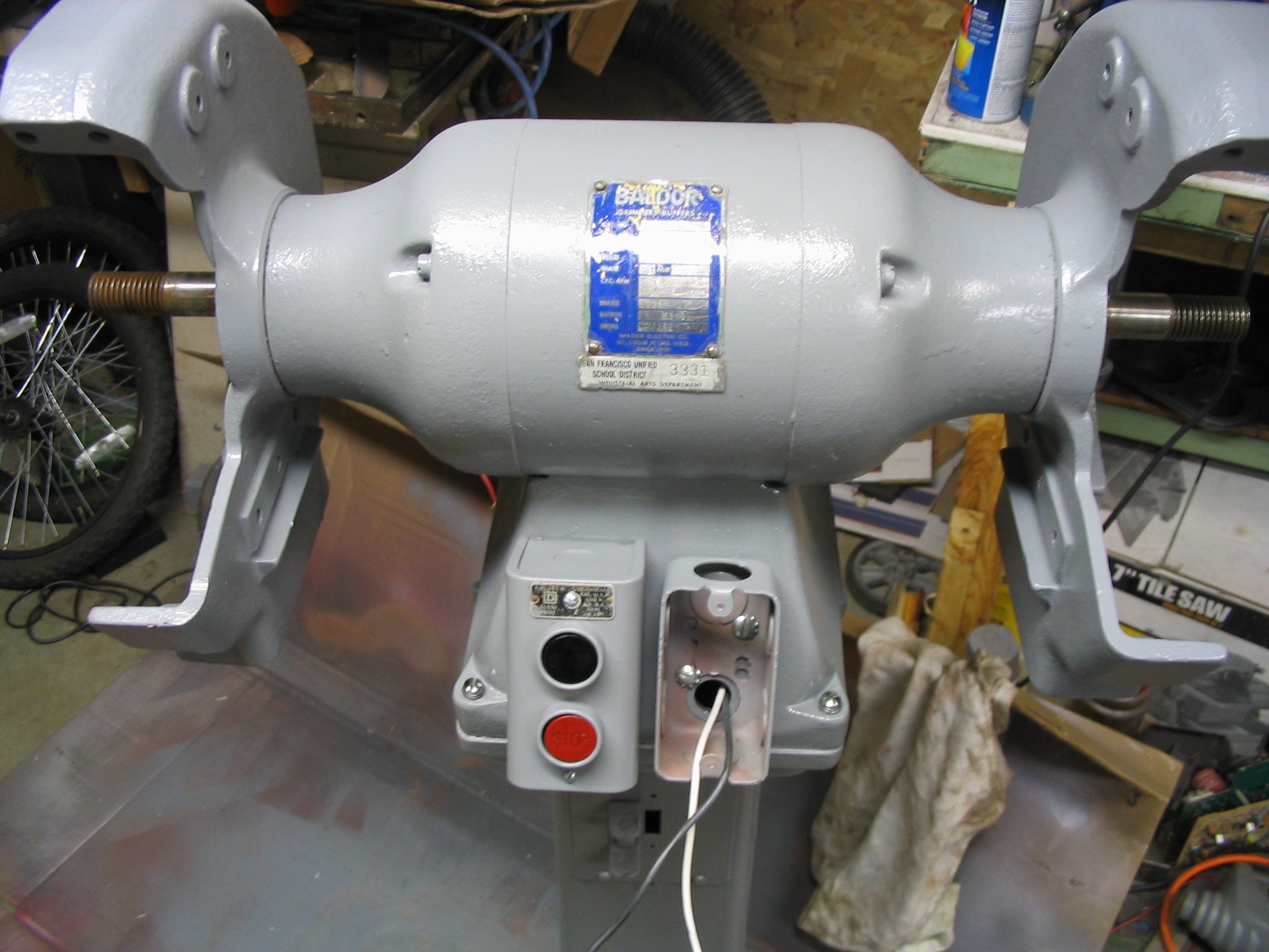
I rewired the relay box to supply single phase power to the phase converter. I attached it to the pedestal stand of the grinder. I drilled holes in the pedestal and tapped screw threads into them, and screwed the relay box in place. Instead of flex conduit for the power line, I added a standard power cord. Since it uses 240 volts, double the US standard, I used a different plug and outlet.
The phase converter needs an extra momentary push button to start the motor, so I added that to the front of the grinder next to the main on-off switch.
3-phase motor static phase converter
 I received a Baldor metal grinder with 10-inch wheels, with a motor wired for three-phase industrial power. Three-phase power is not provided in U.S. residential homes, so I needed to power it from normal single-phase power. My solution was to build a balanced static phase converter, requiring only a few relatively inexpensive capacitors. (Much less expensive than the nuclear reactor I was considering.)
Research and Testing
Electric Motors in the Home Workshop Amazon IndieBound |
I knew I had some homework to do, to figure out how to make this work. I had ignored much information on 3-phase motors in the past, thinking that I would likely never need it. When would I ever come across any 3-phase equipment that would fit my miserly budget? Well, now, it seems.
The first resource I turned to was Electric Motors in the Home Workshop by Jim Cox, my favorite book on the subject. This book is written specifically to address reusing various industrial and appliance motors for home-built tools and uses, which fits my crazy schemes. It covered the basics of 3-phase motors, but did not go into great details. It did describe a very common method of generating 3-phase power from single phase, which is called a rotary phase converter. In this method, you use a single-phase motor to mechanically drive a 3-phase “idler motor” which generates the other 2 phases. This is a robust and flexible method which can handle multiple varying 3-phase loads. It also takes up some room, and requires two large electric motors dedicated to it. If you had a variety of 3-phase motors to run, it is a good solution. But it seemed like overkill for just my one grinder.
 I did some more Internet searching, and came across another idea: the static phase converter. This is a very simple converter which uses capacitors matched to the amperage draw of the motor to generate the extra two phases. As long as your amperage draw does not vary much (meaning you can only really use it for one motor), this is a simple and inexpensive solution to the problem.
I found the best explanation and description in Rick Christopherson’s page on
building a balanced static phase converter. I used his guidelines to determine the likely capacitor values I would need for my converter.
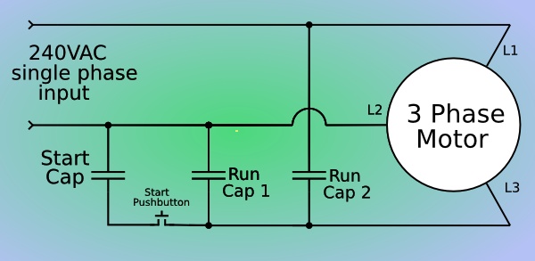
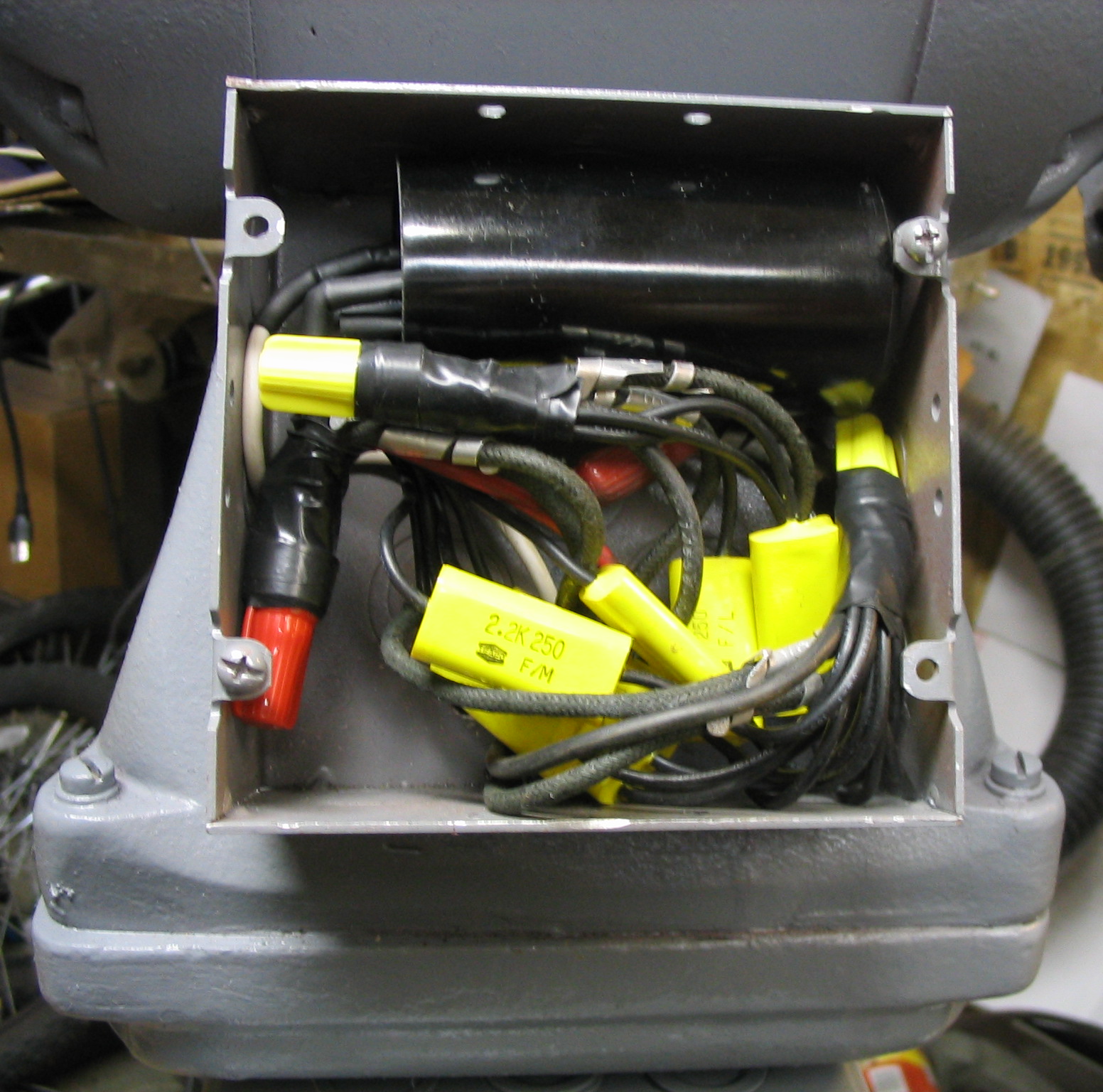
There are two run capacitors for the extra two phases. The two capacitors create pulses 120 and 240 degrees out of phase with the primary, so the second capacitor is twice the size of the first. Based on his tables, I guessed that my motor would require about 6 uF and 12 uF for the two phases.
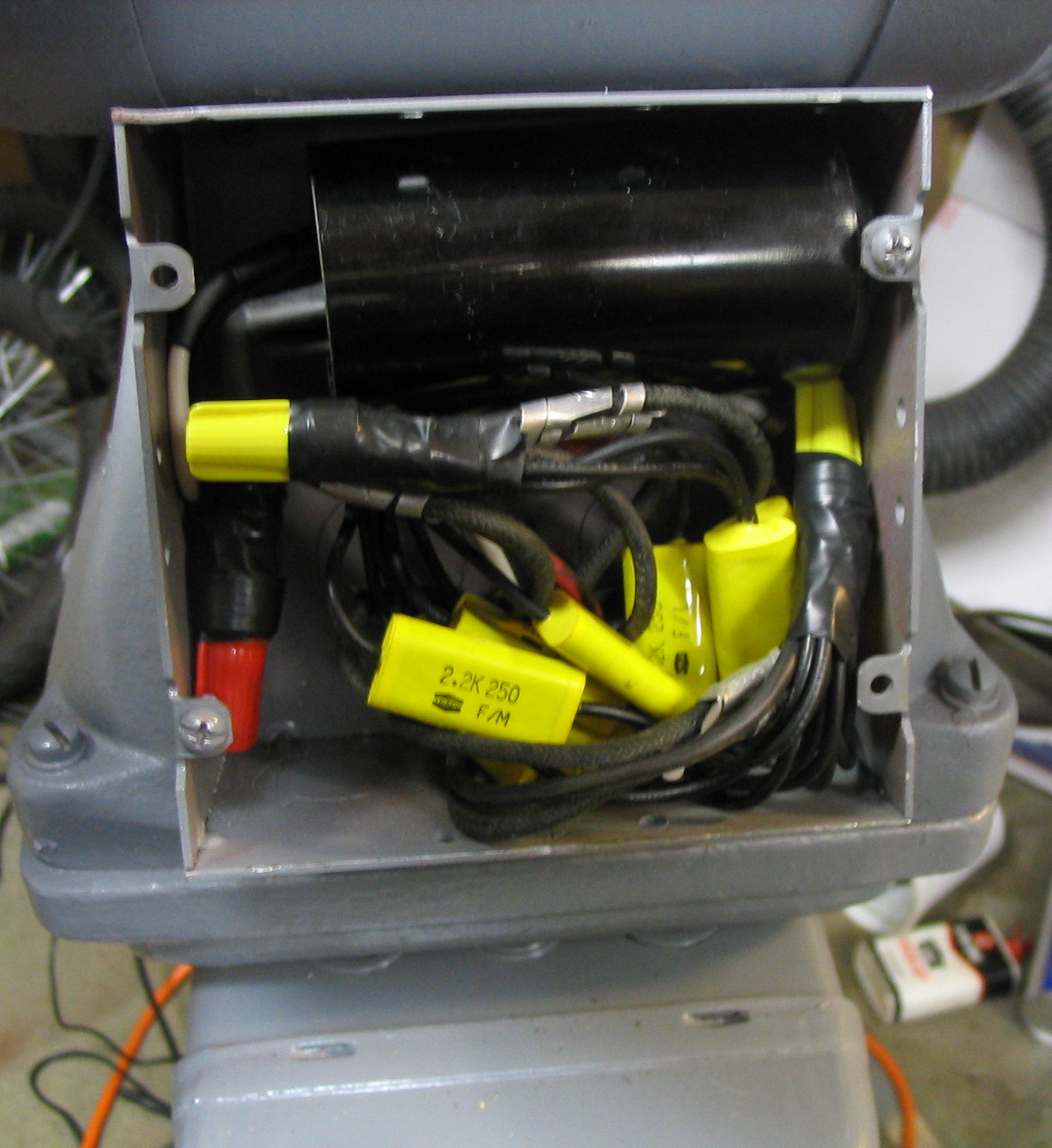
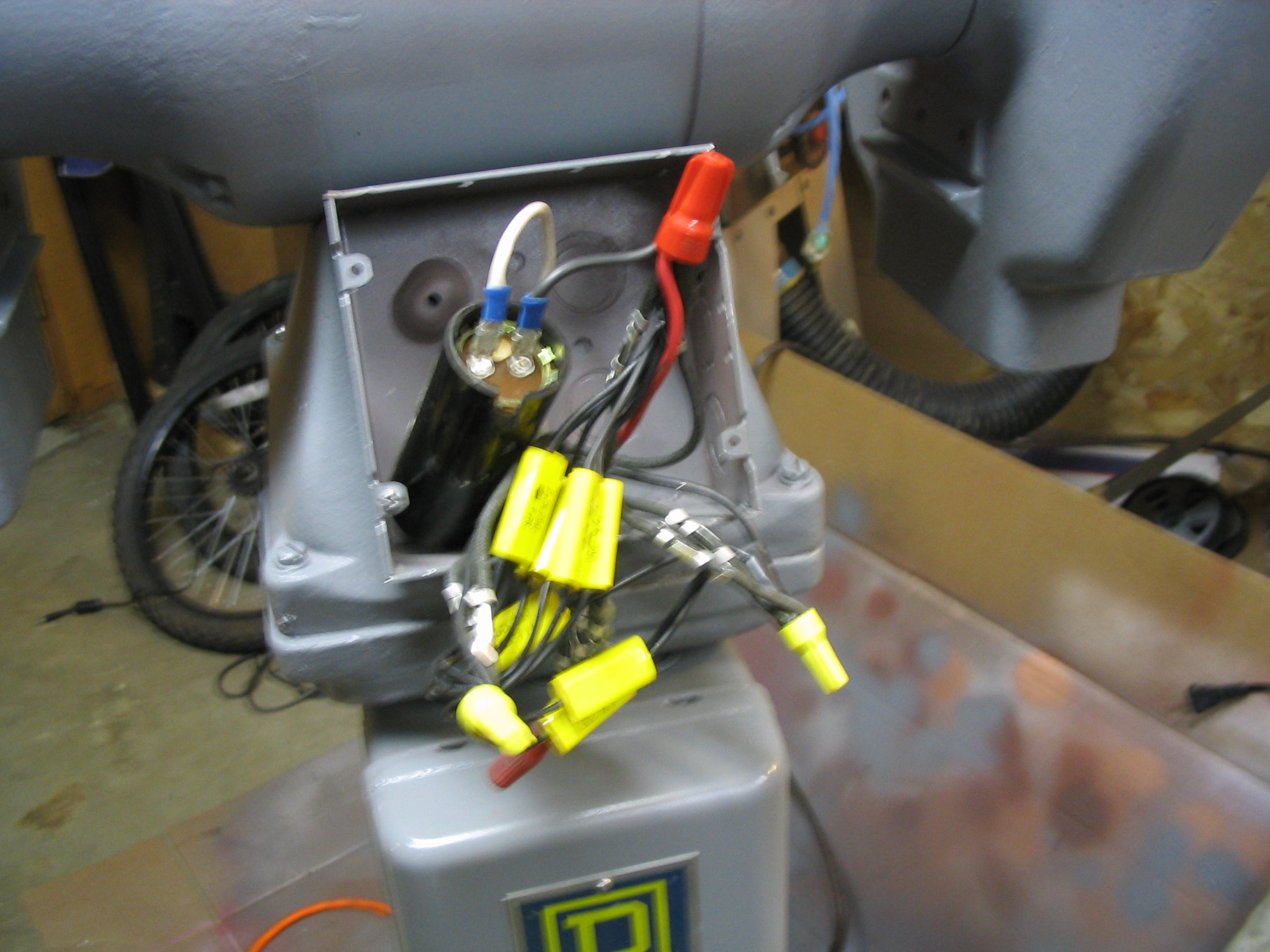
I went to a local surplus store, and was able to find smaller capacitors of 2.2 uF. My electricity textbook said that capacitors can be combined in parallel to add them up, so I just combined 3 for one phase and 6 for the other, providing 6.6 uF and 13.2 uF.
Just putting the run capacitors in the circuit would get it to run, but it would not start from a stand-still. With my dad helping me, we were able to spin the motor axle with a rope to get it started, and then turn on the power to make it continue running. It worked! I checked the power draw of all 3 phases with an inductive ammeter, and they were all nearly identical within 0.2 amps of each other.
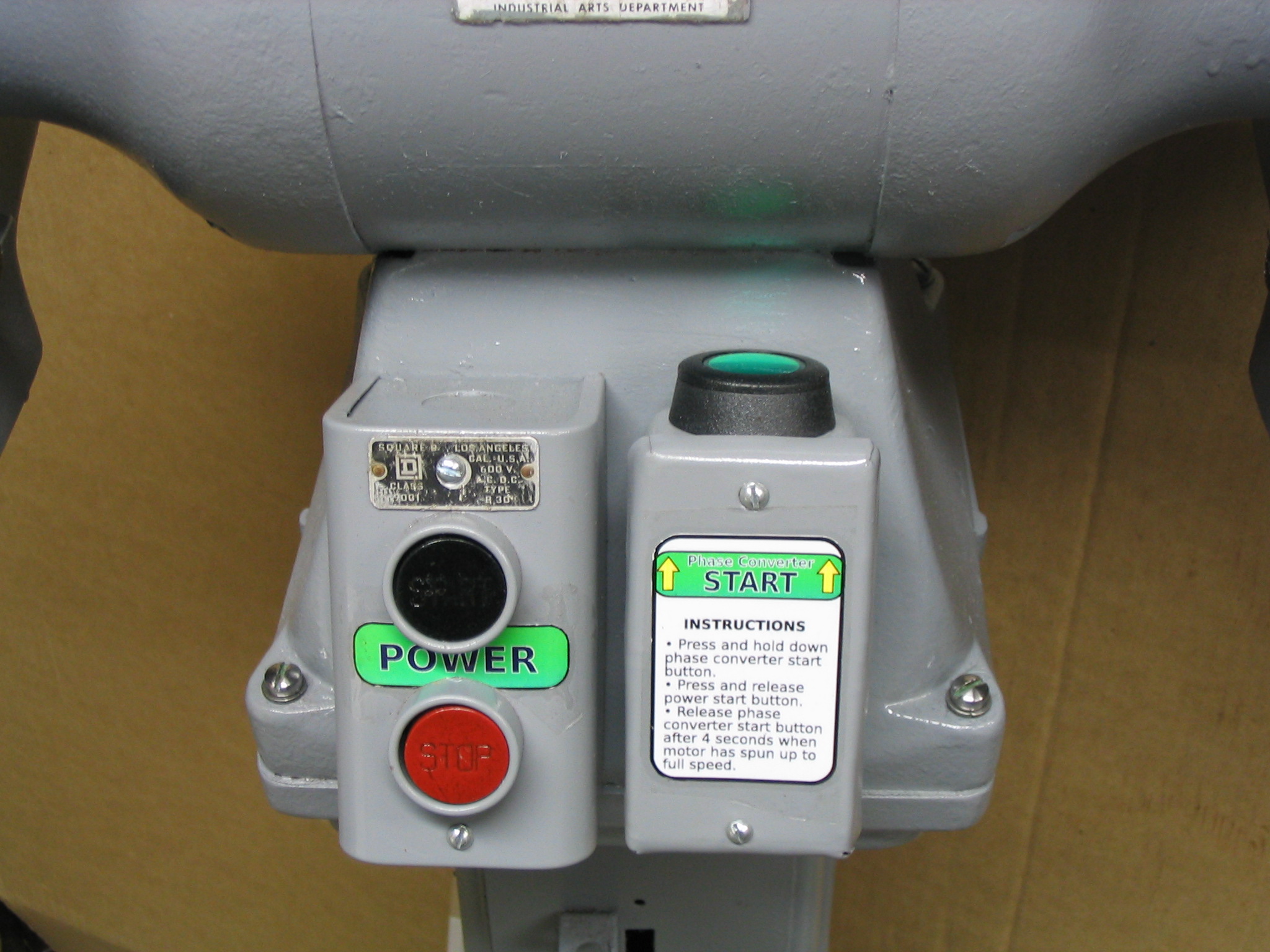
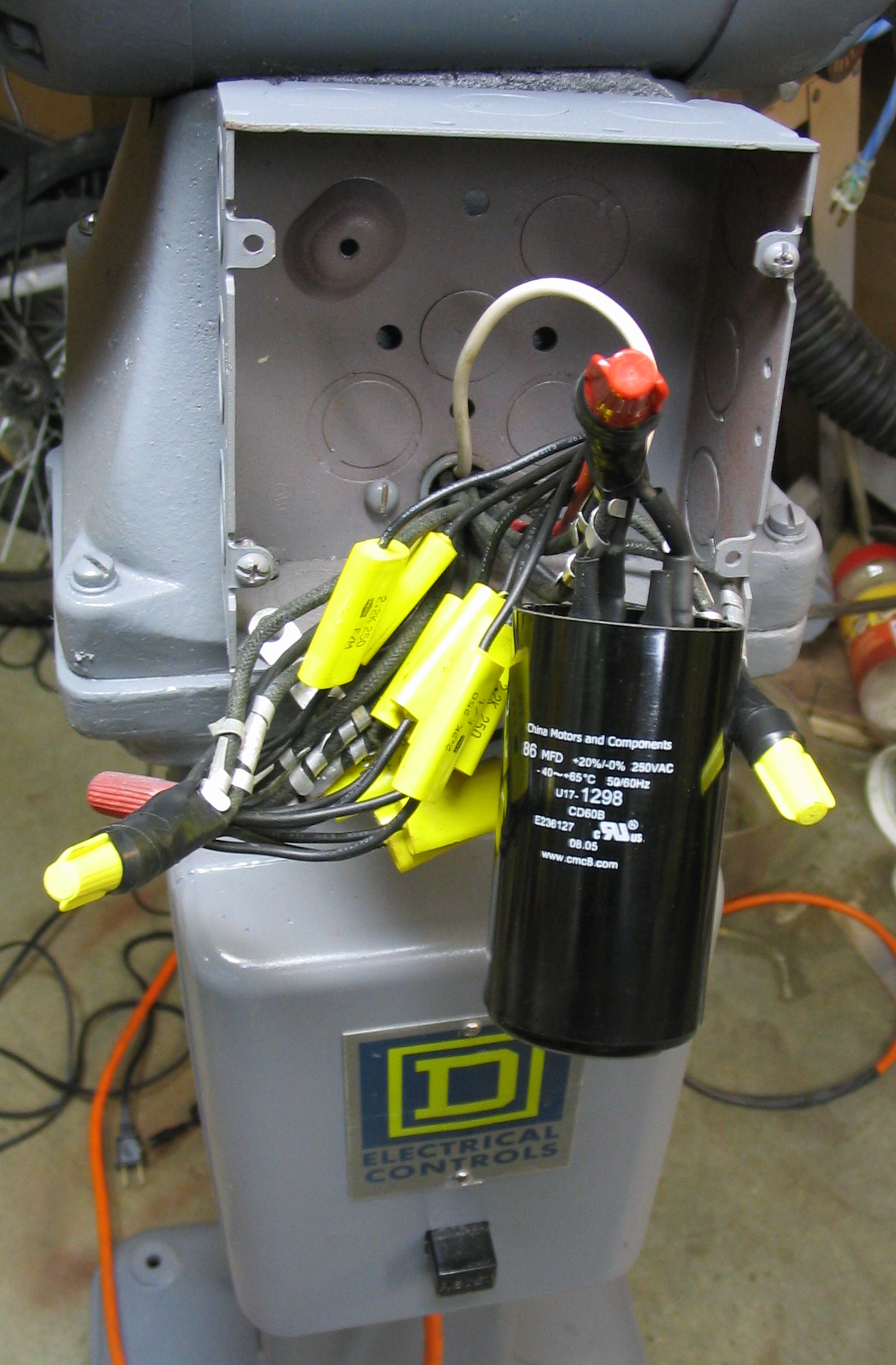 To bring the motor up to speed under power, it needs a large starting capacitor, connected in with a momentary push button. They are readily available, sold simply as A/C start capacitors. I had a capacitor from an old washing machine motor, which worked to start it as a test. I ordered another one of 86 uF from an Internet mail-order surplus place. Holding the start button for about 3 or 4 seconds is all that is needed to bring the motor up to full speed.
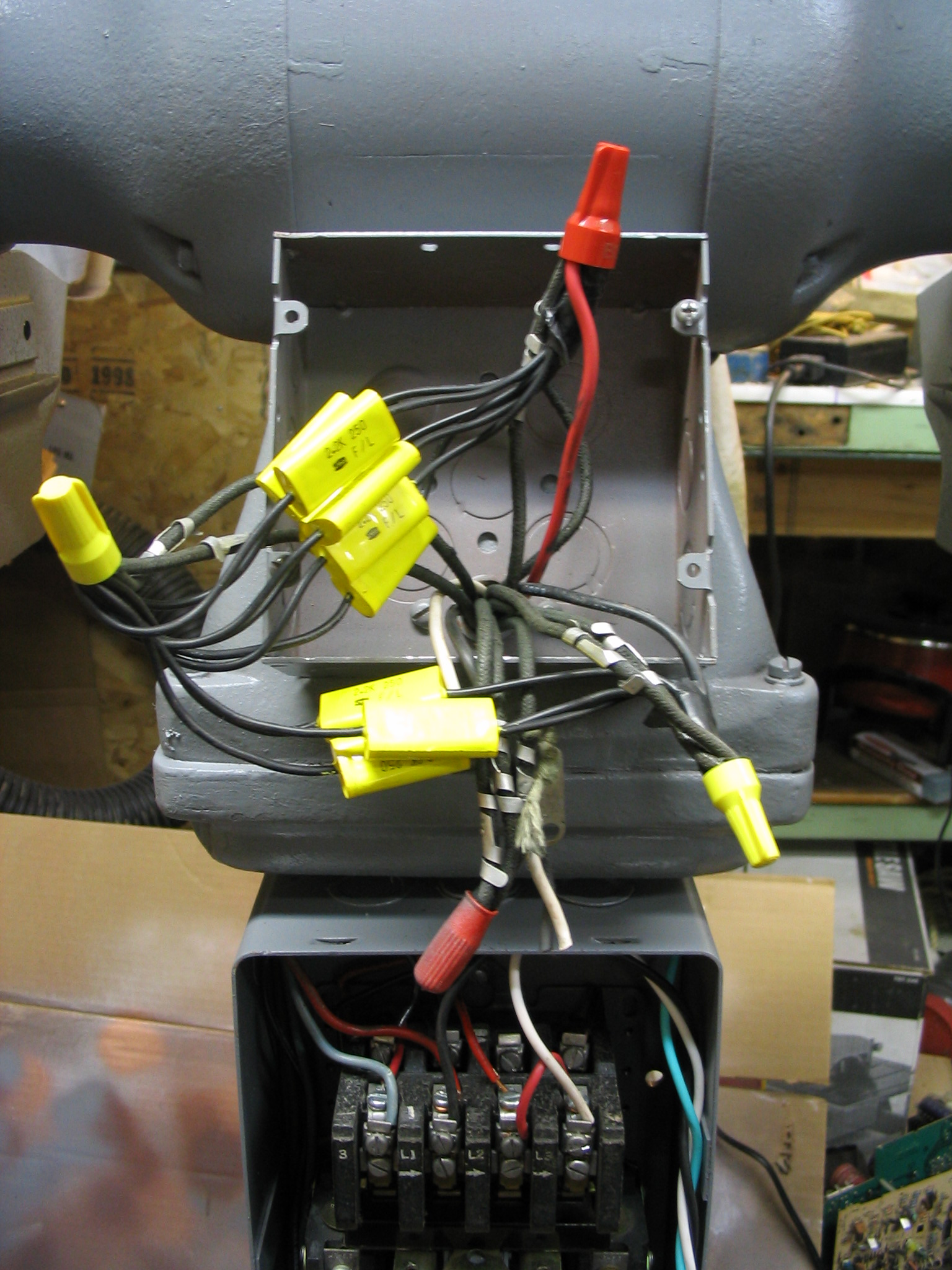
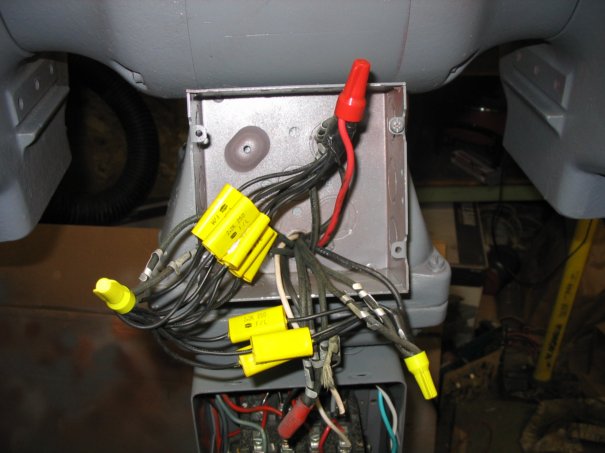
Construction
Figuring out the capacitor schematic and values was the hard part. The rest of the construction was relatively simple. The grinder already came with a large magnetic relay contact switch and circuit breaker, previously wall-mounted separately. I attached it to the back side of the pedestal stand, and put the push-button on/off switch on the front. I added two new electrical boxes: one on the front for the momentary start push button, and one on the back to hold the capacitors.
Since the voltage is double at 240v, I needed a different plug and outlet. But the amperage is low at 5 amps, so did not need a large super-heavy-duty power cord and plug like one might use with an electric clothes dryer or kitchen stove. I found a plug and outlet the same size as a standard US power plug, but with both prongs rotated at 90 degrees from standard, so neither side could be accidentally interchanged with a normal plug. Since the total amperage draw is only 5 amps, a 14-gauge power cord was adequate.
Result
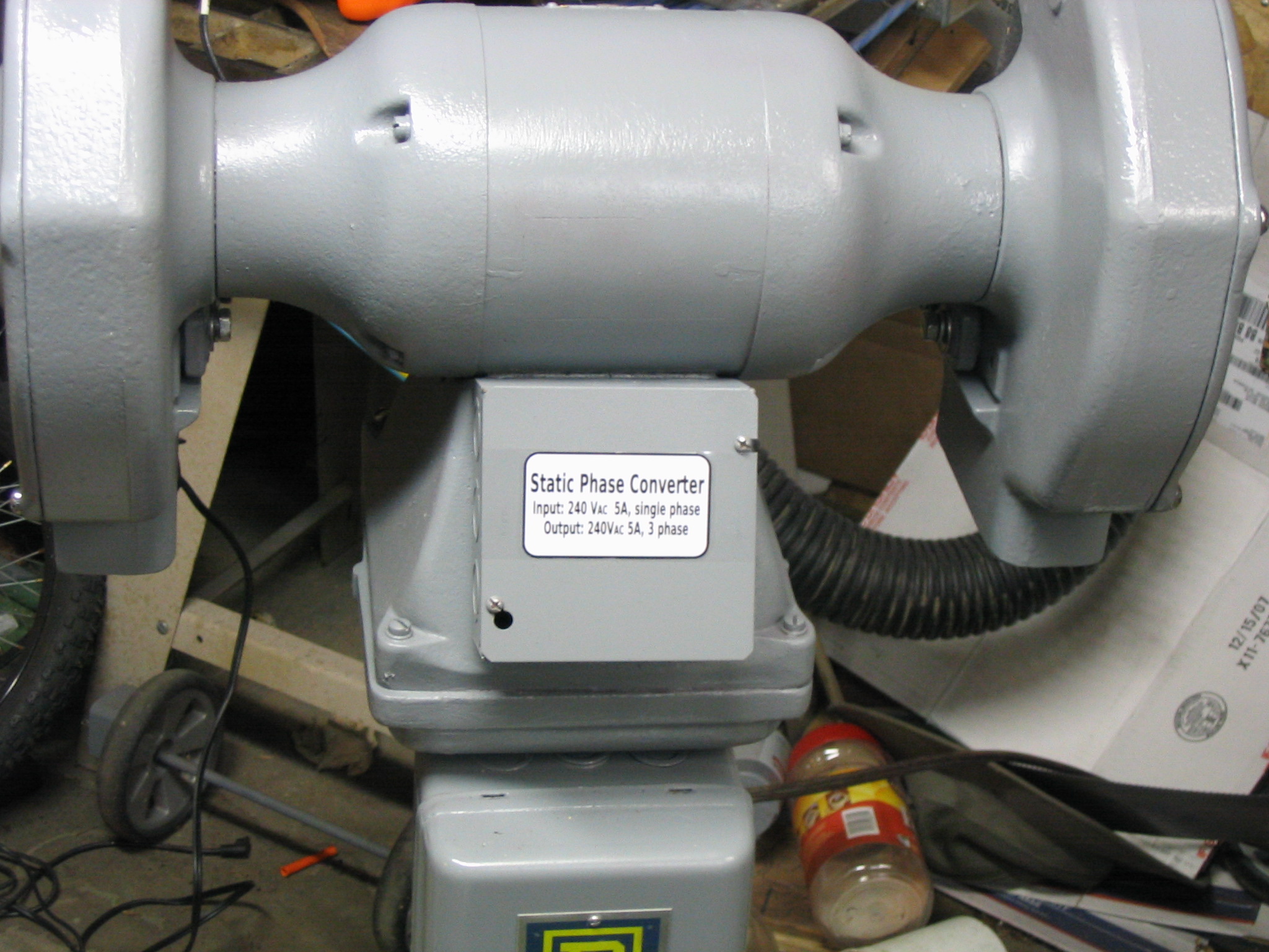 I created some labels using Inkscape, printed them on photo paper, and attached them to the various boxes.
The end result was very satisfying. The motor only takes about 4 seconds to spin up to speed, and the grinder works great.
Submitted by amillar on Tue, 2008-09-16 12:08
Drill press lathe from bicycle hub
Any trained machinist will tell you that a drill press with a cheap jig is no substitute for a proper lathe. I’m not a trained machinist, so now that I’ve said that, let’s get on to accomplishing something interesting.
I recently saw an idea for using a drill press as a simple vertical lathe. If you make a “live center” and attach it to the drill press table, you can do some basic wood turning in a vertical position. A live center is a pointed shaft on a bearing, which rotates with the work being turned on the lathe.
Eccentric Cubicle Amazon IndieBound |
New Wood Puzzle Designs Amazon IndieBound |
200 Original Shop Aids & Jigs for Woodworkers Amazon IndieBound |
This is not a new idea. One has been sold commercially for years as the Vertilathe, and Grizzly sells a lathe attachment for a drill press also. It has shown up in several books, including “200 Original Shop Aids & Jigs for Woodworkers” by Rosario Capotosto, “New Wood Puzzle Designs” by James Follette, and “Eccentric Cubicle” by Kaden Harris.
Needless to say, I had to try it out. If you want to make one like me (which of course you don’t because such endeavors are both tedious and hazardous), you might (or might not) do it as follows:
- Acquire a bicycle wheel. This will be found rusting next to the apartment dumpster, or perhaps readily retrieved from the neighbor’s garbage can. Do not take the wheel off your neighbor’s working bicycle; they will frown upon this. Make sure you grab the cheap wheel with nuts that hold it on a solid axle, not the one with the cool and coveted lever clamp through a hollow axle. (Actually, snag that one too, but keep it for later.)
- Remove the spokes from the hub. If you got the rusty one from next to the dumpster, you’re in luck because half the spokes will snap right off quite easily. If you are impatient and/or feeling destructive, use some heavy wire cutters to clip the remaining spokes. If you are feeling a little more retentive, remove the tire and unscrew the nuts holding the spokes to the rim. Toss the spokes and rim into the nearest metal recycling bin. We don’t need them for this project. If we need some for another project later, well there’s no shortage of rusty bicycle wheels in the world, now is there?
- Disassemble the hub and axle. Unscrew the nuts on each end of the axle. You should find that both ends simply unscrew, and that the axle is just one long threaded rod. Behind the nuts there should be some ball bearings. Take it all apart and soak it with your favorite rust remover, such as WD40. Don’t use water; it isn’t a good rust remover.
- Clean the parts. Use a rotating wire wheel to remove the rust from the hub, axle, and nuts. Chuck the wire wheel into the drill press and start cleaning the parts. You do have a drill press, right? This lathe jig isn’t going to work with a hand drill. And don’t accidentally clean your fingers with the wire wheel; it hurts. Don’t ask how I know.
- Put a point on the axle. Use a grinder or file to make a rough point on one end of the axle. Then chuck the axle into the drill press and use a file to make it nice and pretty. And centered. That’s more important than the pretty part. Mostly.
- Grease and reassemble. Load up the bearings with grease and reassemble the hub. Just like those Brady boys on TV, working on their bikes instead of riding them. OK, I never actually saw them reassemble a hub on one of their bikes. In fact, while they appeared to be working on their bikes, I don’t think I ever saw them actually fix anything. Hmmm.
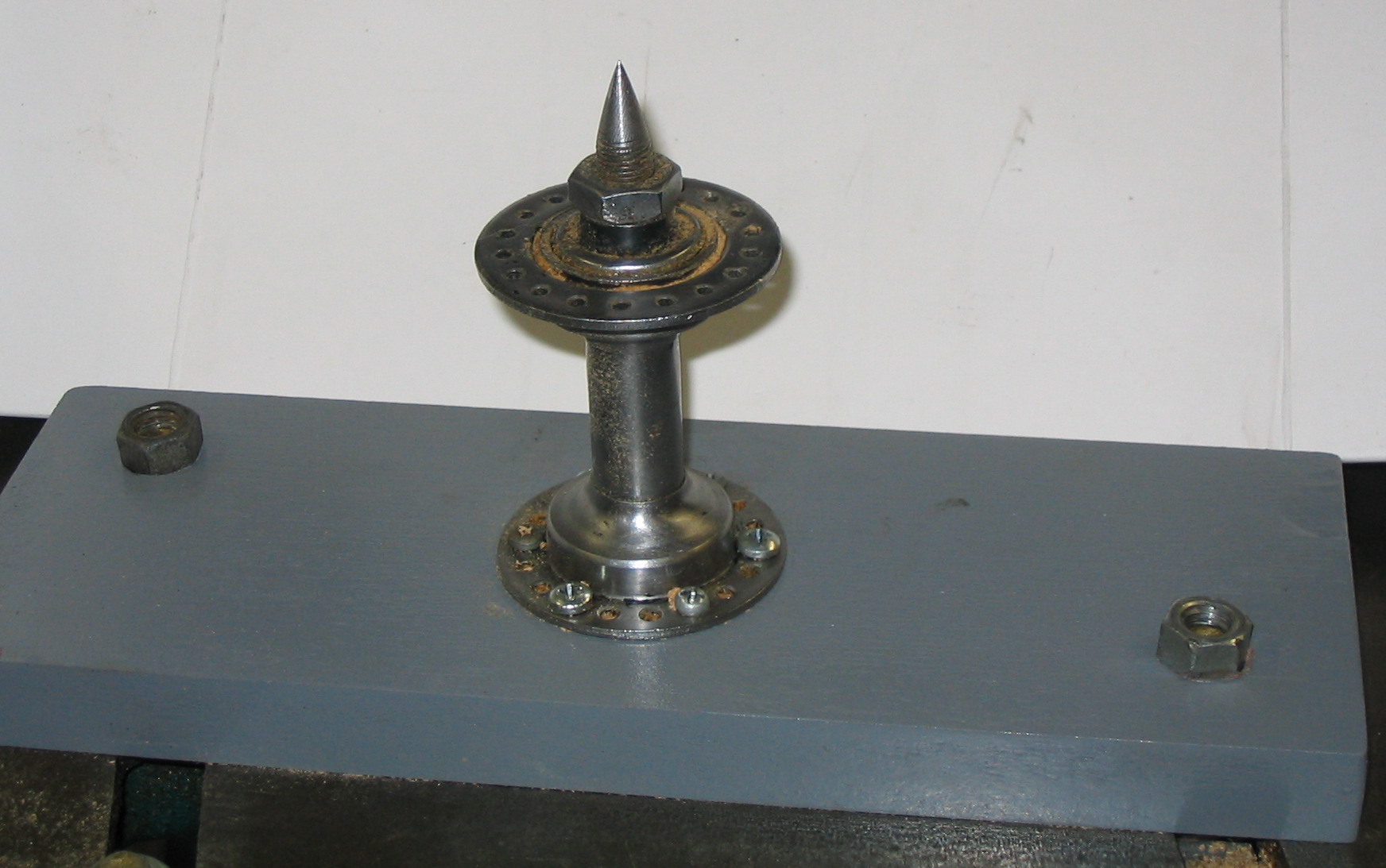
Once you have done all this, you will have a rather hazardous-looking sharp pointy bolt that rotates. My wife says it looks like something Speed Racer would have coming out of the side of the Mach 5, so he could pop the tires of the other cars in the Grand Prix. Why were all the races always called the Grand Prix? Aggh, stupid TV. Where was I?
Now we need to hold it to the drill press table.
- Cut a piece of wood to size. Make it fit the size of your drill press table, so you can clamp it or bolt it down. (This is where those cool bike axles with the lever clamp come in, if you were lucky enough to find some.)
- Drill a hole in the center. Make it large enough to fit the other end of the axle, which will stick through the wood and drill press table. We want the axle to rotate freely, and not bind against the wood. That would defeat the whole purpose of those fancy ball bearings in the hub, now wouldn’t it?
- Paint the wood to look official. Perhaps a nice gloss grey, just like they would do in the Navy when using a piece of wood and an old bike wheel to make a lathe out of a drill press. Ahem.
- Screw the hub to the wood. OK, the real part you were waiting for. Put some screws through a couple of those little spoke holes in the hub to secure it to your fancy-pants painted board. Make sure the screws don’t go all the way through the wood and scratch up your nice drill press table.
Congratulations! You have built yourself a live center. You have now completed half of the project. You’re in good company, because I’ve only completed this much also. I’m too impatient to wait, so let’s see some results now.
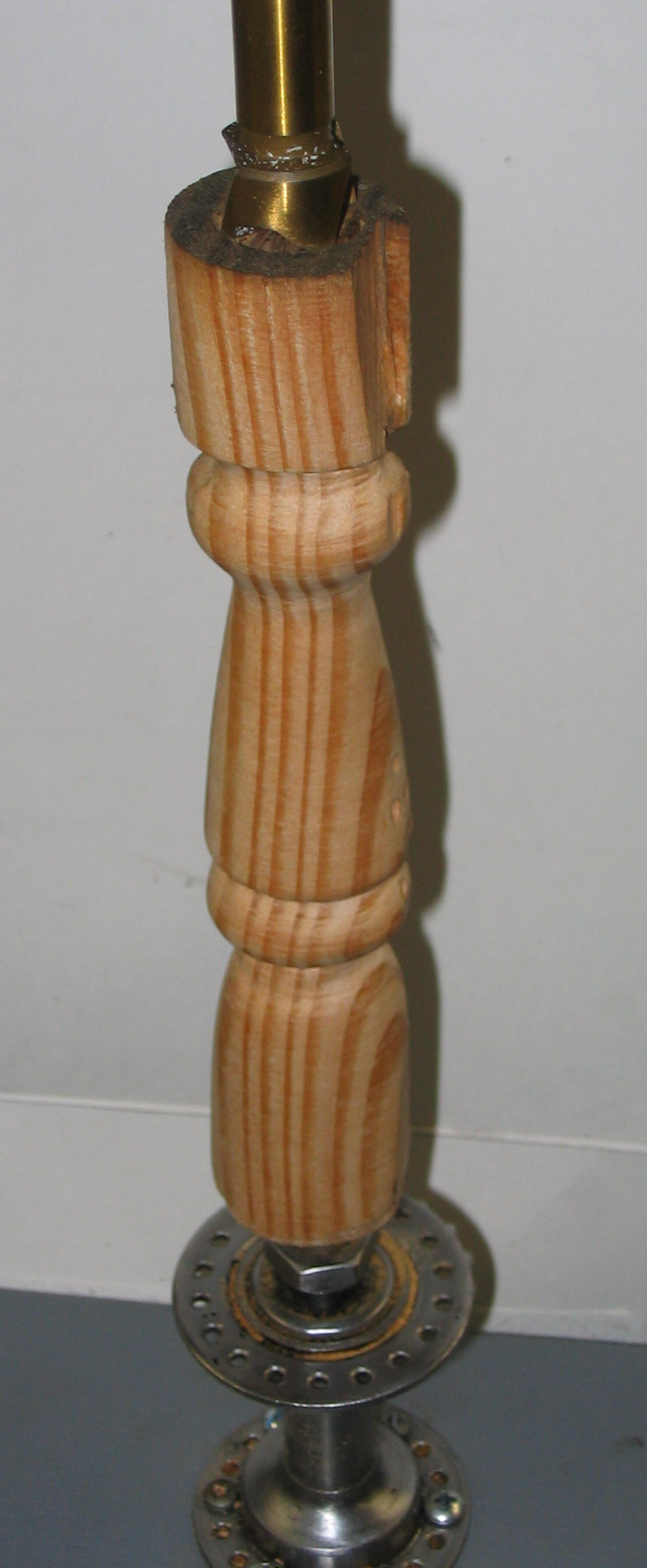
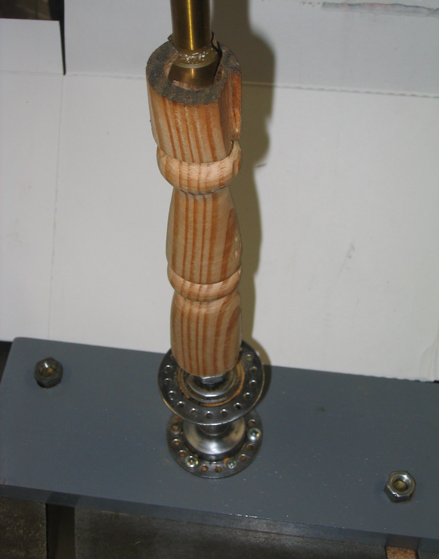
Line up the live center on the drill press table directly beneath the chuck, and clamp it down to the table. Put a wood screw into the top of your piece of wood and chuck up the screw, or chuck up a Forstner drill bit to press into the end of the wood. Raise the table or lower and lock the chuck to hold the wood firmly between the chuck and the live center. Now you can spin the wood. Give it a short spin, then tighten the gap again after the live center presses into the bottom of the piece.
Spinning wood is fun, but shaping it is even more fun. We are only half done, because we don’t have a tool rest to use for any carving tools. But I can’t wait that long, so we can use a wood rasp and files for some quick wood turning results.
This is the point where you go read up on safety somewhere. Holding a jaggedy rasp against a spinning piece of wood is a recipe for having a tool thrown at a vulnerable spot on your person, or some other such hazard. Seriously, be careful with this stuff.
Having said that, the rasp and files actually work nicely. Using combinations of straight, half-round, and rat-tail files, you can actually produce a moderately interesting piece of turned wood with this little jig.
Soldering/Brazing Aluminum
Yes, you can solder/braze aluminum. No, you can’t use regular solder or brazing rod.
Tablesaw dust collection with shop vac
Many woodworkers have dust collection systems, which use suction and large pipes and hoses to collect sawdust and other particles from power tools. For the hobbyist, these systems can be affordable, below $1000 for a decent system. Naturally, I therefore wondered what I could accomplish with my old shop vacuum, some junk from the garbage can, and about 20 bucks.
Woodshop Dust Control Amazon IndieBound |
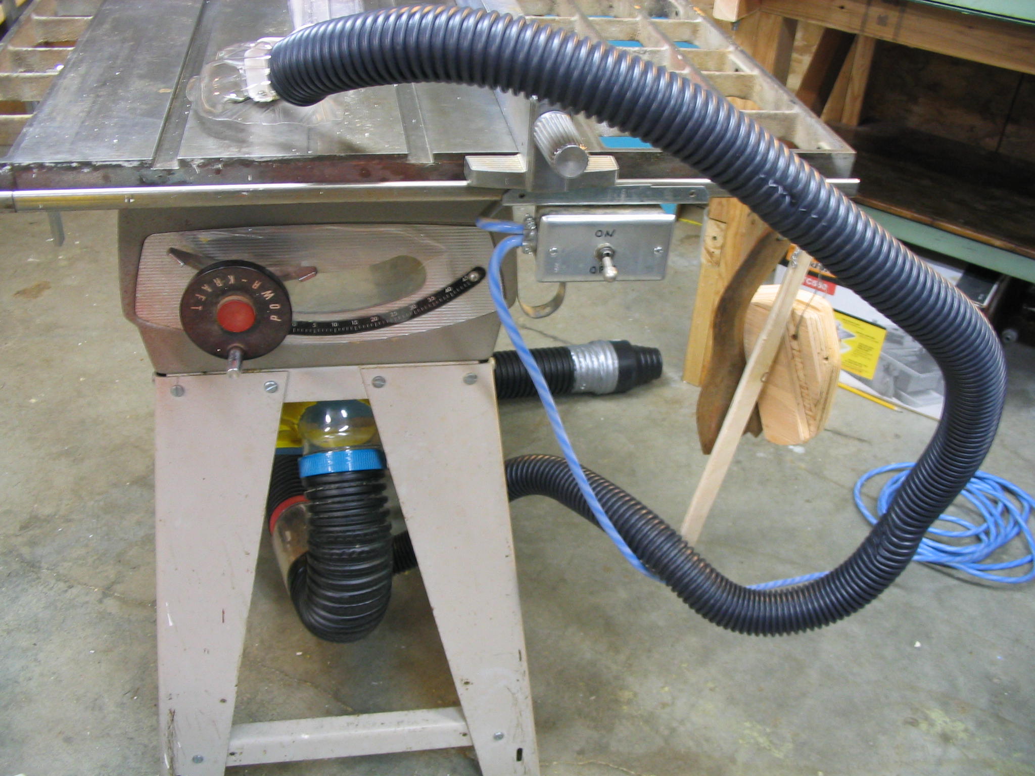
The basic premise is to collect sawdust, trimmings, and other particles as close to the source of production as possible. Many power tools come with dust collection ports built in to them these days. My 1950s PowrKraft table saw did not, so I set out to create a dust collector for it.
The Tablesaw

My tablesaw was not designed for vacuum collection of sawdust, so it has quite a few openings which needed to be covered. The underside of the saw is open, with a sheet-metal rim around the inside. This made a good place to attach a collection hood. I fabricated one from a rectangular plastic bucket made from HDPE (high-density polyethylene) plastic, the most common type used in common buckets and consumer packaging.
Since the bucket had a hinged snap-on lid, I turned the bucket upside down and used the lid as the bottom of the dust hood. The lid then became an access door to the underside of the saw. I used the heat gun to bend the sides of the bucket and weld on extra corner tabs, creating flanges to sit on the rim of the saw opening.
Tubing
For the dust-collection tubing, I took the cheap route. I used 3-inch water drainage tubing and 1.5-inch sump pump tubing, both from the local home improvement warehouse store.
Neither one of the tubing sizes I used matches the hose of my shop vac at 2.5 inches, so I needed some adaptors. Several different plastic jars from peanut butter and applesauce turned out to be very close to the correct size. The opening on the applesauce jar was just a little too small, so I made a spreader jig with some wooden wedges between some nuts and washers. When one of the nuts is tightened, the washers squeeze the wedges, forcing them outward. I wrapped the wooden wedges in a piece of sheet metal from a tin vegetable can, and placed the mouth of the jar over it. By softening the jar mouth with the heat gun, and tightening the nut, I was able to expand the jar to fit the vacuum hose just right. I attached the 3-inch tubing to a hole I cut in the bottom of the jar on the other end, making a nice hose adaptor.
What’s That Noise?!
I put two dust collection points into the tablesaw collector: the large main 3-inch hose in the collector hood, and a second 1.5-inch hose to pick up stray sawdust from the top of the table. I attached them together with a Y-connection made from a plastic peanut butter jar. The 1.5-inch hose came out of the side of the jar, but I heated and warped the jar to make a Y connector for better airflow through the smaller hose.
The first time I turned on the shop vacuum with this setup, I got a big surprise. In addition to the usual loud shop vac whine, I got an additional loud piercing whistle noise from the 1.5-inch hose. Some Internet research told me this was a “standing wave” harmonic vibration, caused by the uniform ridges in the hose. The factory did an accurate job of creating all of the ridges in the hose the same. When air passes through the hose, the ridges cause the air to vibrate at the same frequency all along the hose, causing a single tone to come out. It’s one big whistle.
Ironically, my web search efforts revealed much about how to produce such a noise, but not how to surpress it. However, some thought and experimentation led to a simple answer: If the uniform ridges make the whistling noise, making them non-uniform should eliminate it. I heated the hose with the heat gun, and stretched it by different amounts at different points along the hose. It didn’t take much stretching to disrupt the harmonic effect, eliminating the shriek and producing quieter air flow.
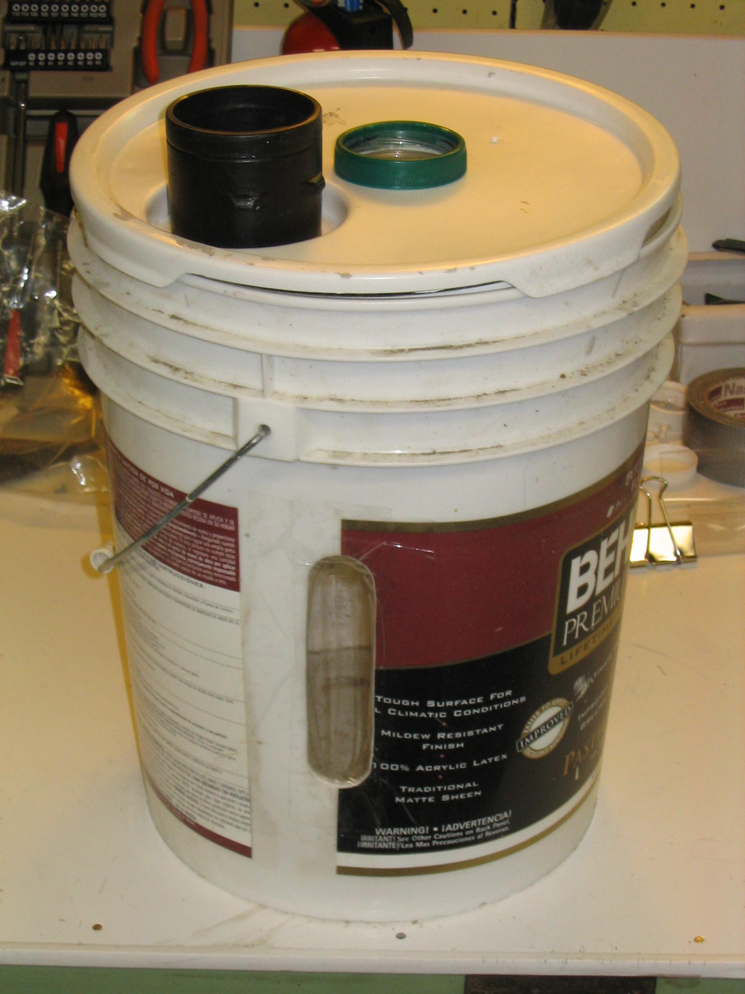
Particle Separator
I use the tablesaw to cut both wood and plastic at different times. I want to keep the two separated so the wood sawdust can be used for composting, without being contaminated by plastic pieces.
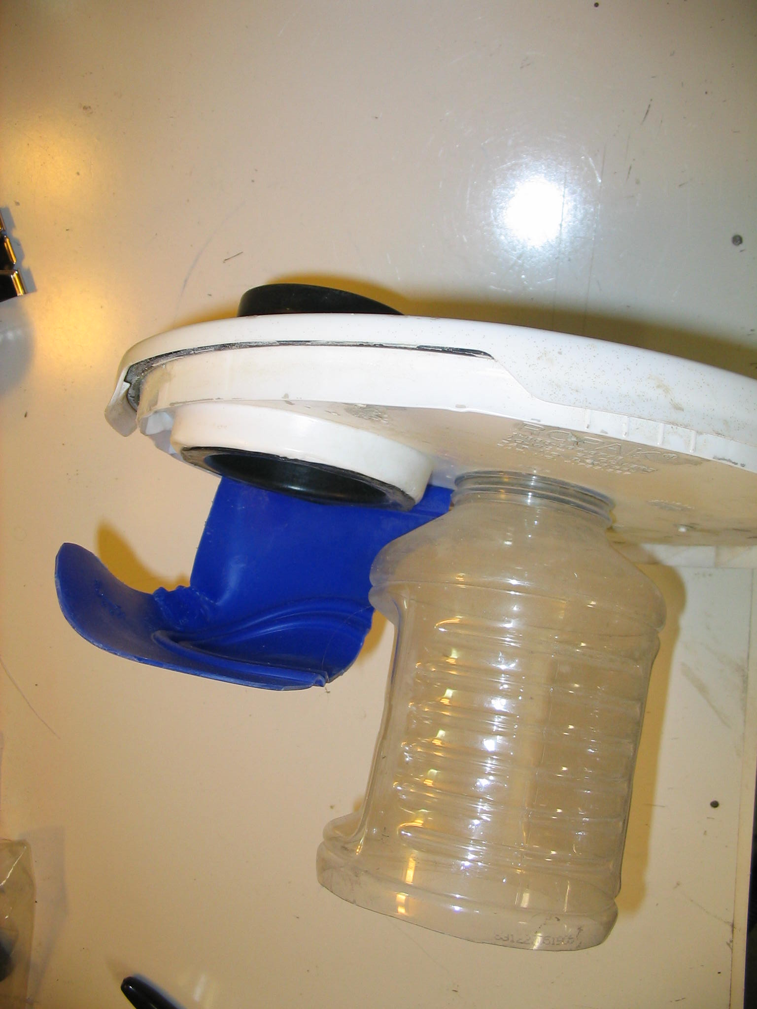
I made a pre-separator to collect the wood sawdust using a 5-gallon paint bucket. The separator bucket sits between the tablesaw and the shop vac. Scraps and larger sawdust particles settle to the bottom of the bucket, while the air and fine dust pass through to the vacuum. It is patterened after professional cyclone separators, where the incoming airflow is directed towards the side of the cylinder and the air exit is in the center. As the particles are blown towards the sides, they lose velocity and swirl down to the bottom.
There are just a few parts to the separator. The vacuum port (air exit) has a tube going down the center of the cylinder, which I made from a clear plastic applesauce jar with a mouth sized to the 2.5-inch vacuum hose, screwed into the bucket lid . The intake port goes to a deflector which sends the air towards the inside wall of the bucket. The intake port is a snap-on connector for the drain tubing, and the deflector is a scrap of plastic. Since the tube connector, deflector, and bucket lid are all HDPE plastic, I welded them together with the heat gun. I also cut a window into the side of the bucket, to indicate how full it is.
Now when I cut wood, I plug the vacuum in to the separator, and my wood cuttings are collected in the bucket. If I want to cut plastic, I bypass the separator and suck the plastic scraps right into the shop vac.
Airborne dust filter
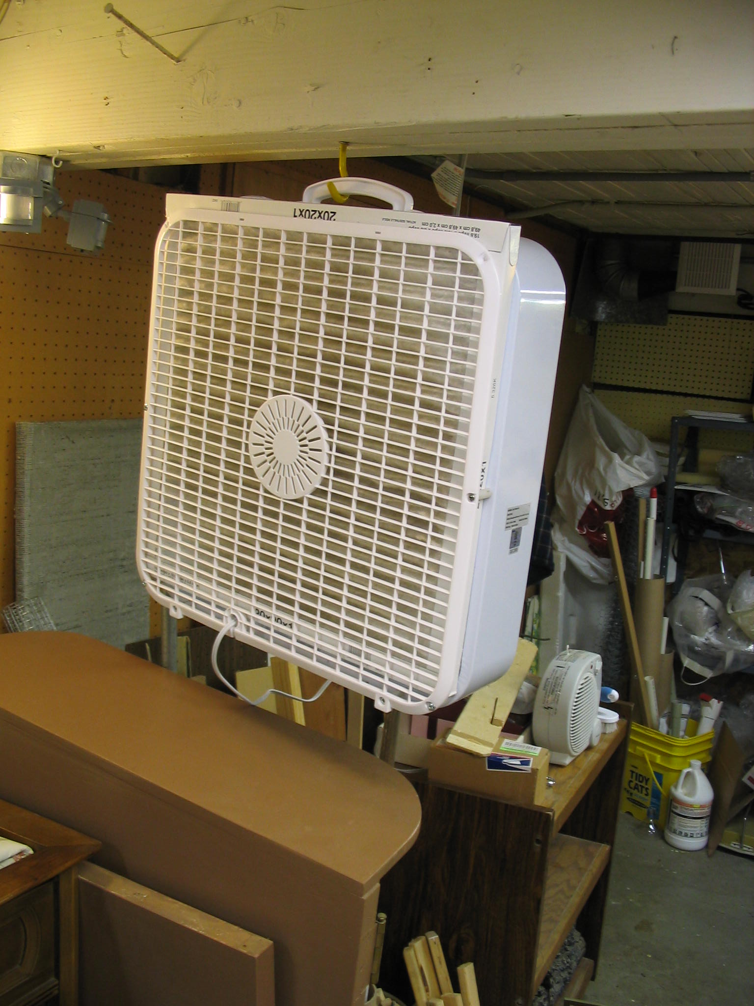
To reduce airborne free-floating dust, I employed a trick which I saw recently in a home improvement magazine. I took a normal household box fan, and attached a furnace filter onto the intake side of the fan. I took the plastic grill off the intake side of the fan and reattached it with spacers and longer screws, allowing me to simply slide the furnace filter into the slot. It works quite effectively, producing a nice brown circle on the filter in no time at all. This is good, showing dust that is not getting inhaled or settling on everything else.
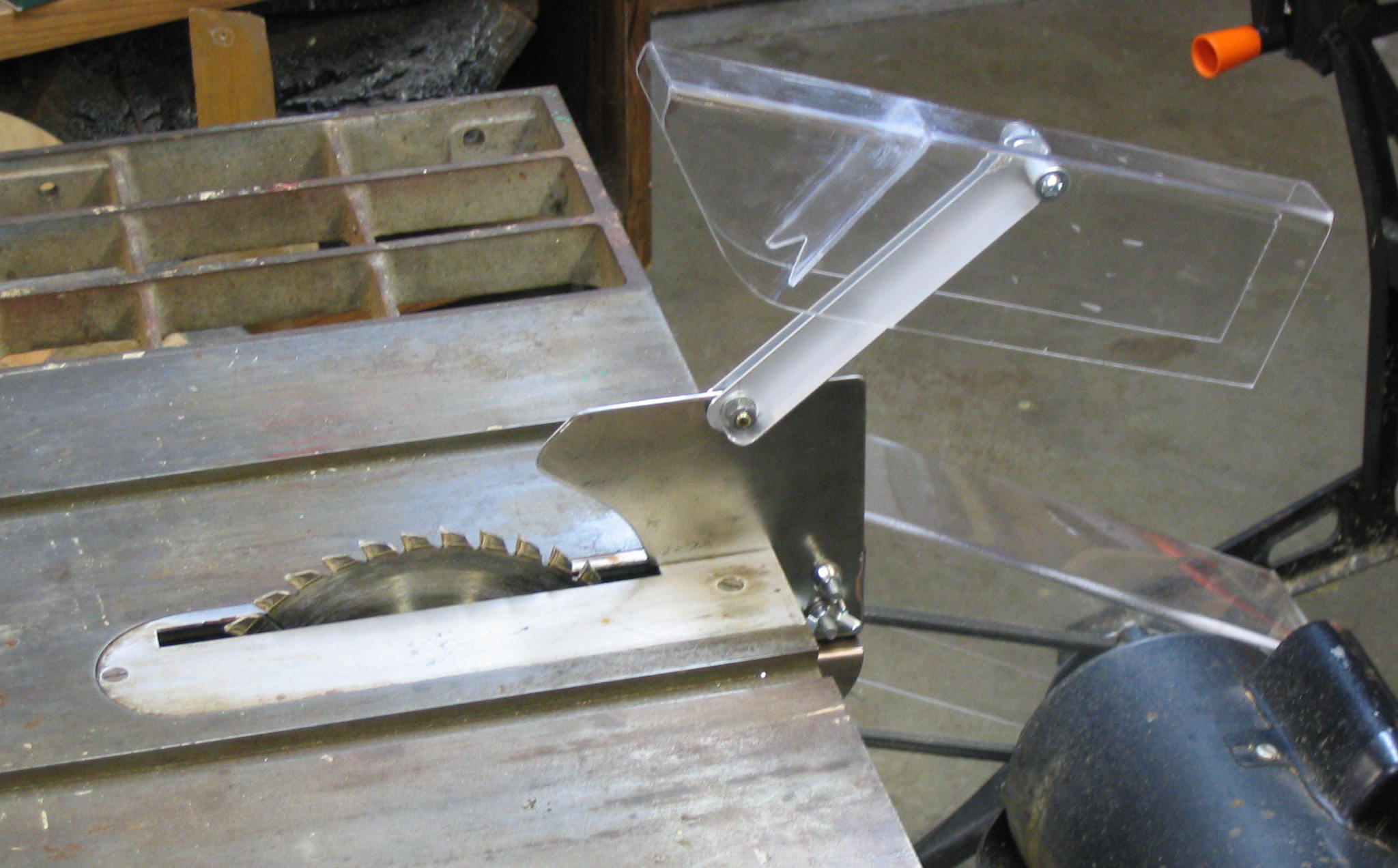
Tablesaw blade guard
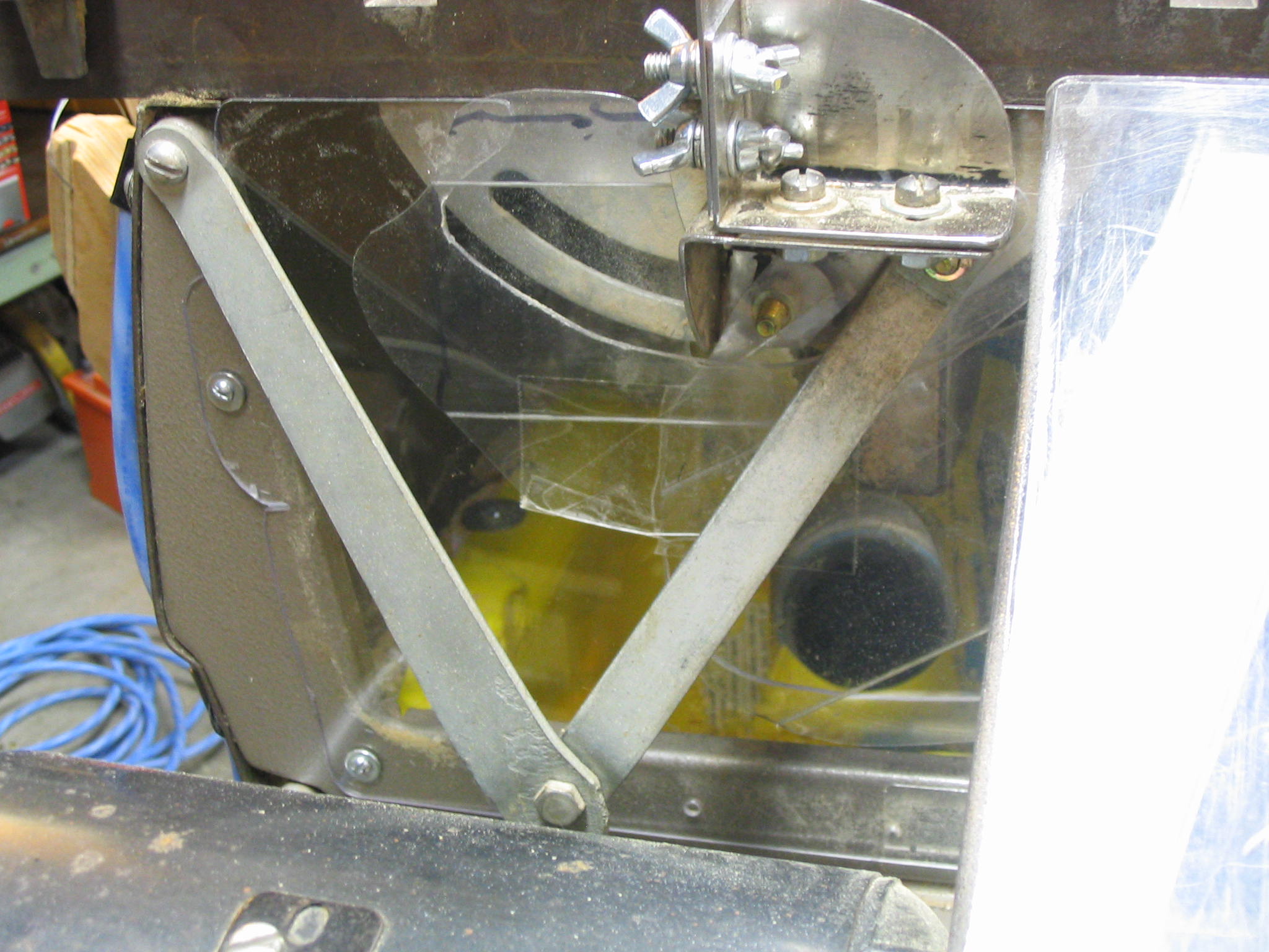
After I made the mounting bracket, then I proceeded to create the blade guard and splitter.
The blade guard has two main components. The cover goes over the blade, to prevent the saw operator from getting injured directly on the spinning blade. The cover is usually made of clear plastic, and is attached to the splitter. The splitter is a vertical piece of sheet metal sitting behind the blade, which guides the cut wood past the blade so it won’t bind.
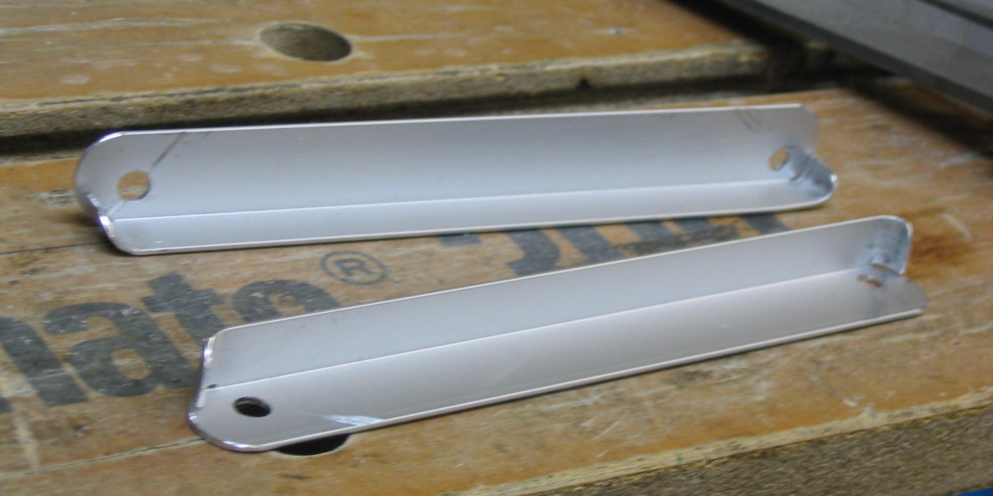
Splitter
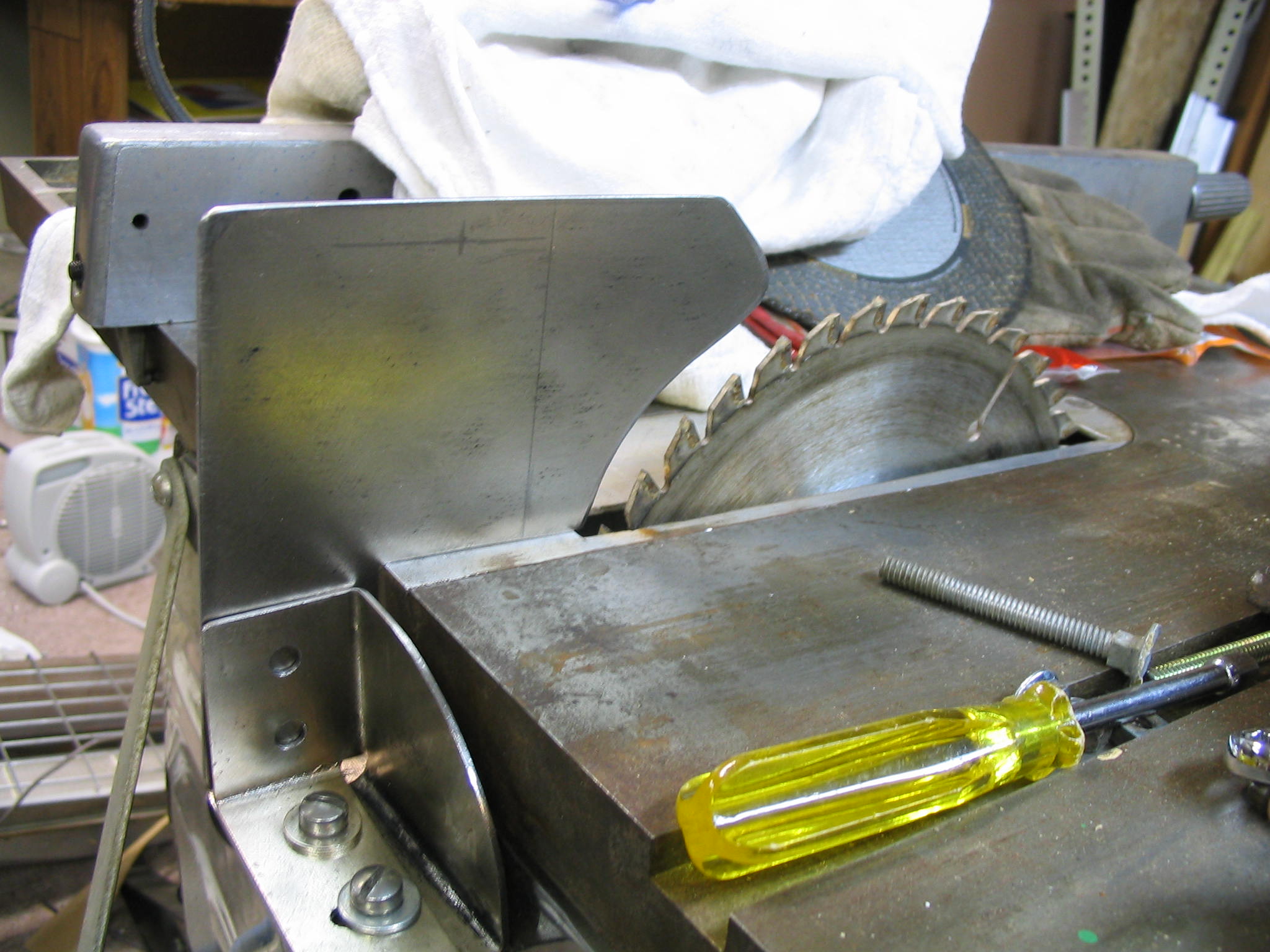
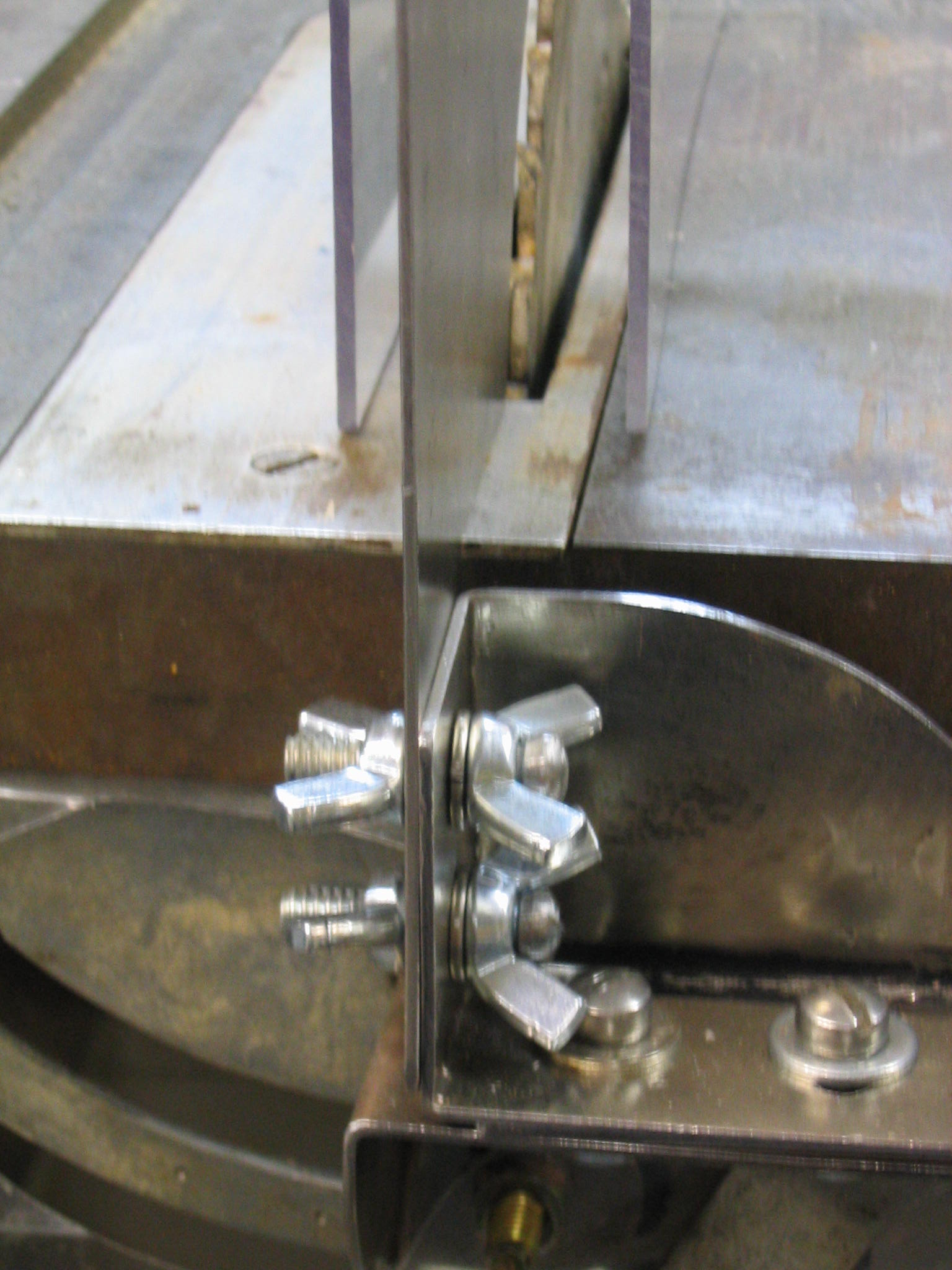
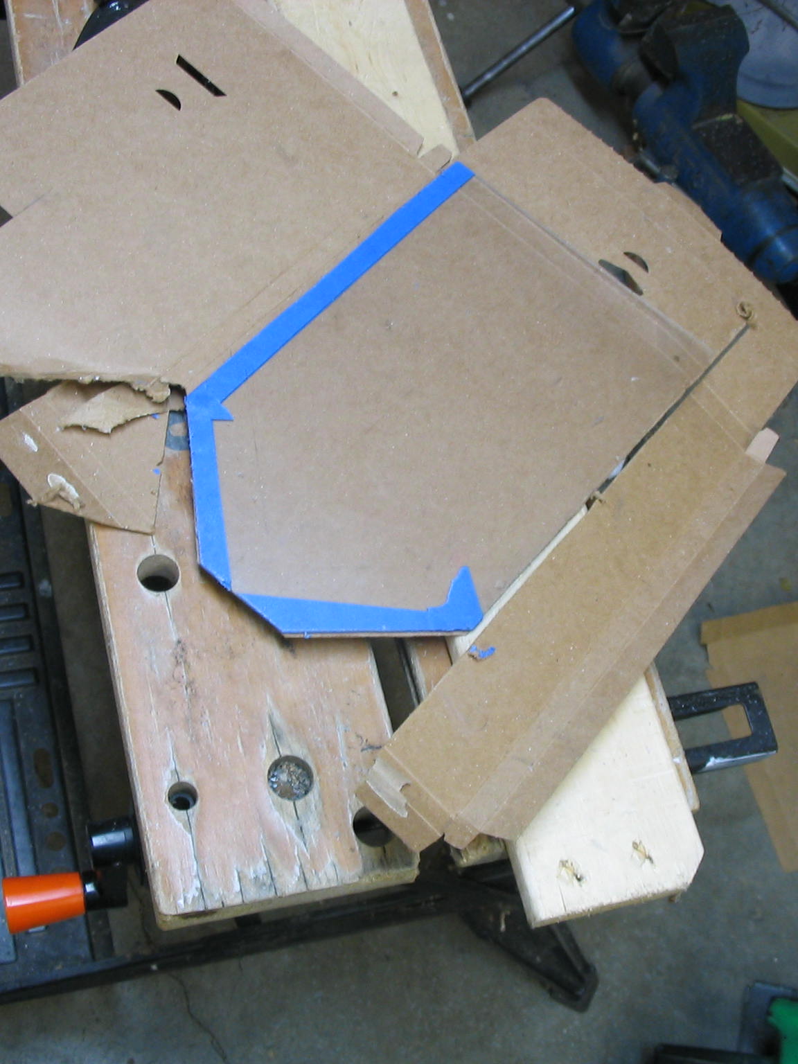
I made the splitter out of the same heavy sheet metal I used for the mounting bracket, 1/16″ steel. I used the same process, where I made a cardboard template first. That way I could ensure that I had the proper positioning on the table saw bed and around the blade, and I could make the bolt holes line up with the mounting bracket. I used 1/4″ holes and bolts on the mounting bracket, but used slightly larger 5/16″ holes on the tail of the splitter that attaches to the mounting bracket. The holes are just enough bigger that I have some adjustability in the positioning, but still have a secure fit with the bracket.
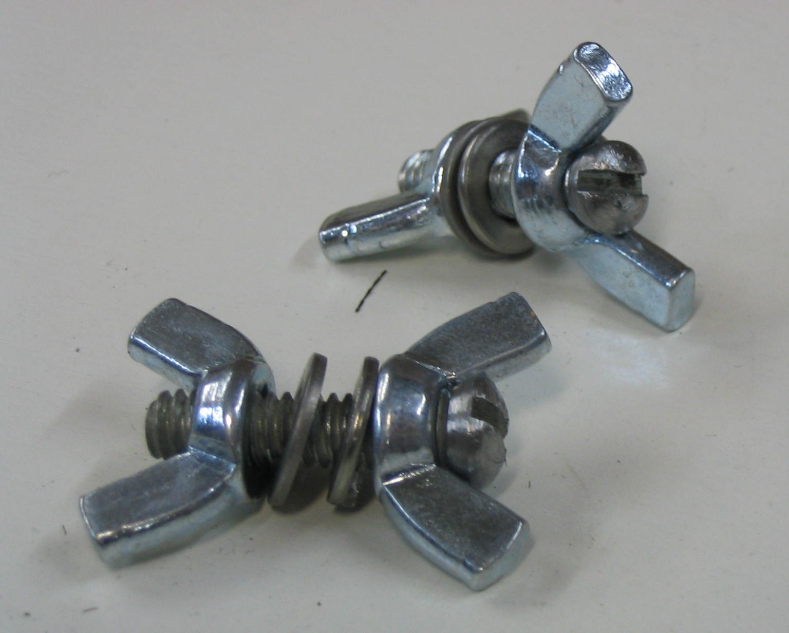
The splitter/guard should be removable for different saw operations like dadoes or shaping. Wing nuts make it easy to remove the splitter without requiring any tools. You can buy bolts with wing heads on them, but I already had extra wing nuts so I decided to put them on both sides. I had screws of the right size, but the screw heads were too wide to fit in between the wings. A lathe would be the ideal way to reduce the screw heads, but I don’t have one, so I put the screws into the chuck of my electric drill and filed them down while it spun.
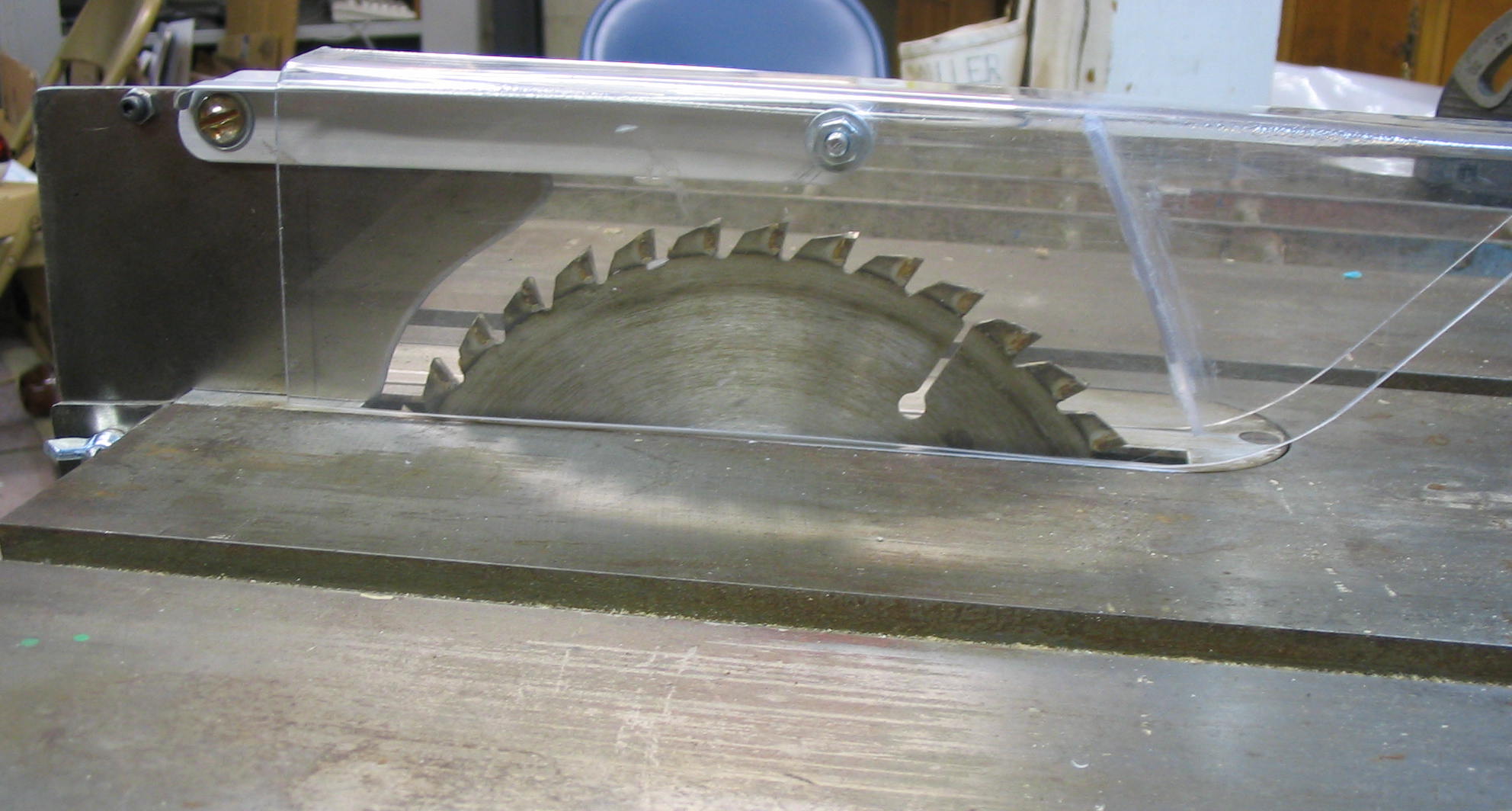
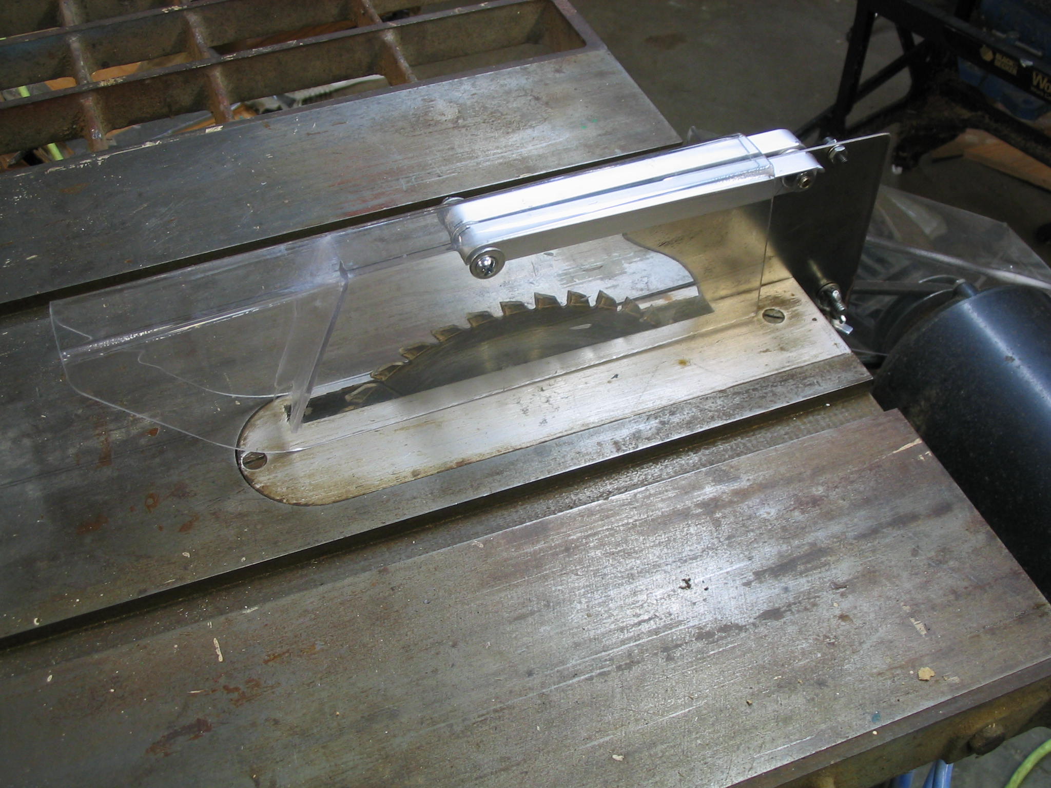
Cover
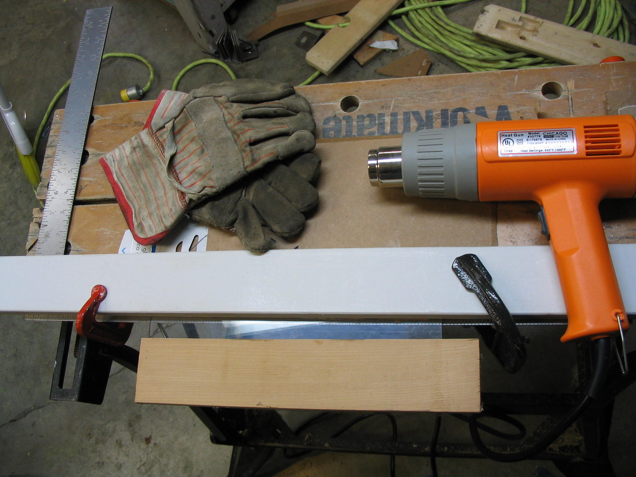
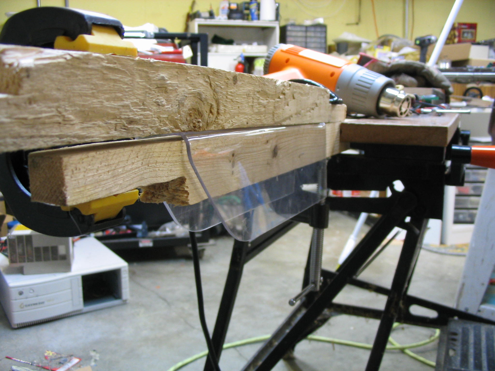
The blade cover is made of clear Lexan polycarbonate plastic, which I think is a better choice than acrylic because it is shatter-resistant. It covers the top, sides, and front of the blade.
When you buy sheet plastic, it usually comes with a paper covering on both sides. This reduces scratches and also reduces chipping along the saw cuts. Since I was working with a salvaged piece of plastic from another project, I placed masking tape along the saw lines to reduce chipping, and put cardboard around the sheet to protect it from scratches and scrapes.
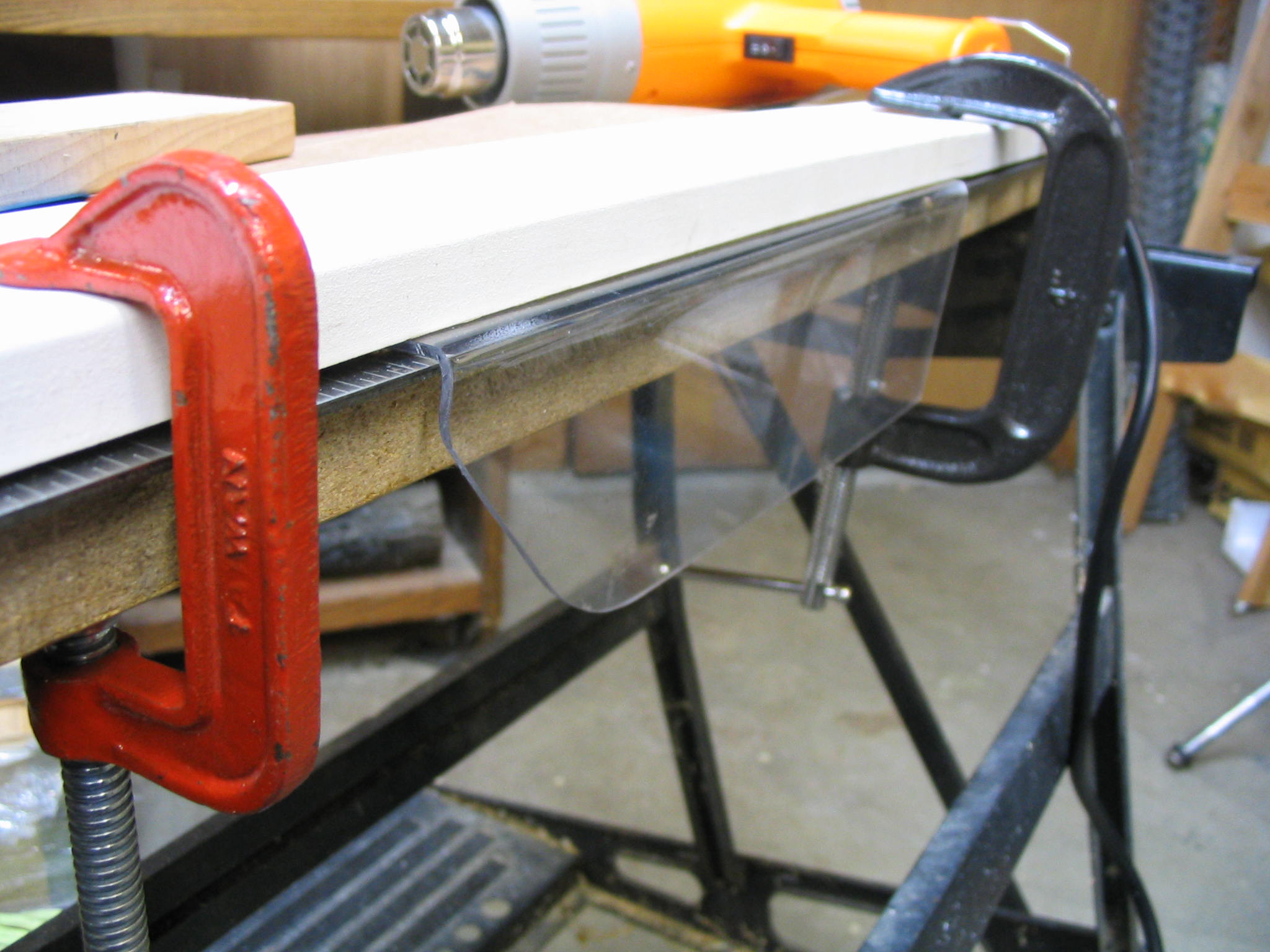
I bent a piece of Lexan into a U-shape channel using the heat gun, making two 90-degree bends. To make the bend, I clamped down the plastic between two boards, and used a metal straight-edge to bend on. I used another board to cover the rest of the plastic, leaving only a small strip of the plastic exposed between the two boards. I heated that strip by moving the heat gun back and forth along it, until the plastic became soft enough to bend. It is still a little hard to get both angles square, so I used another board which was the exact width of the channel. I reheated the corners and pressed the sides flat, producing a decent square channel.
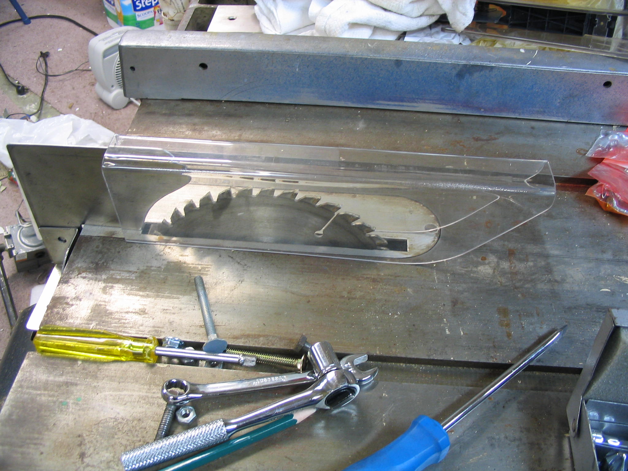
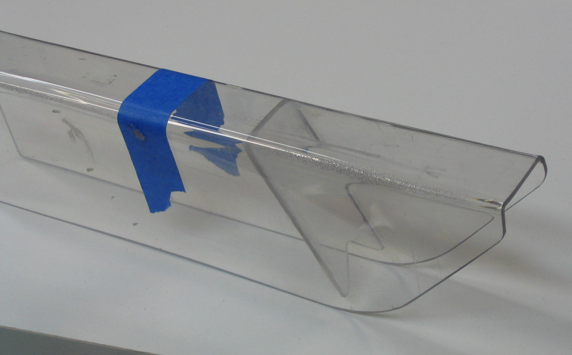
This covered the top and side, but not the front. Since the saw blade spins over the top toward the operator, it is useful to cover the front to prevent any chips from being flung forward. I cut out another piece of Lexan and filed it to fit the channel, and glued it with cyanoacrylate “krazy glue”.
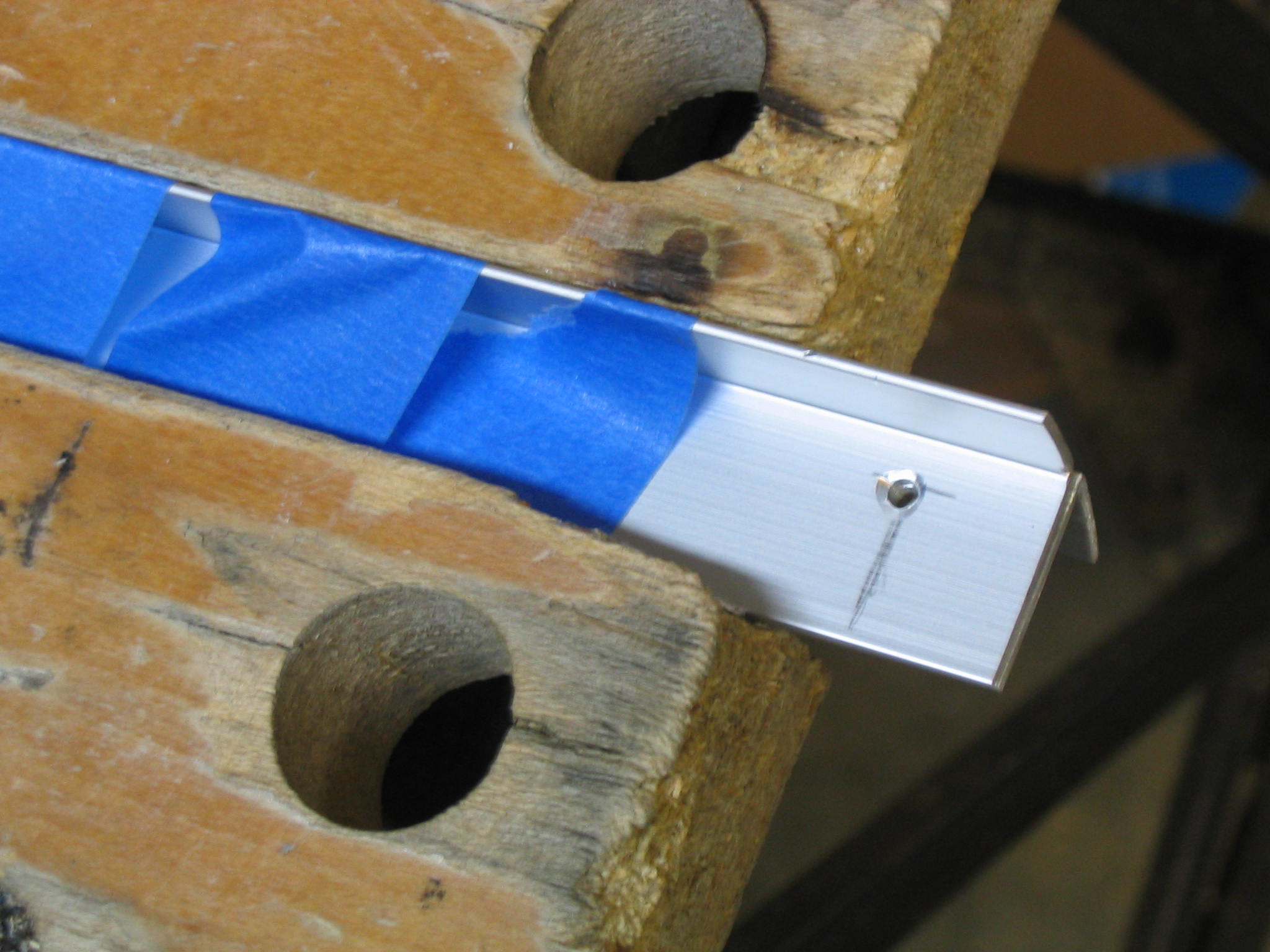
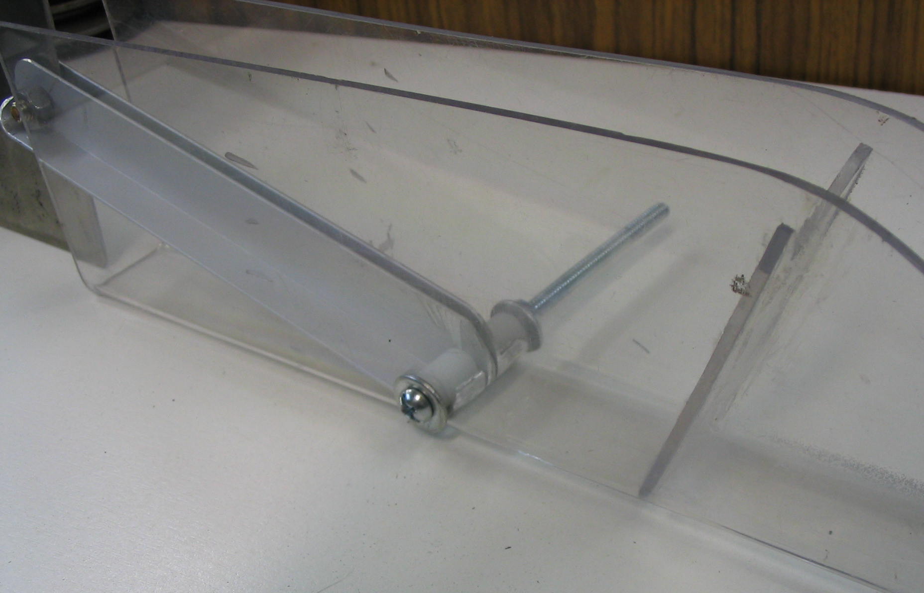
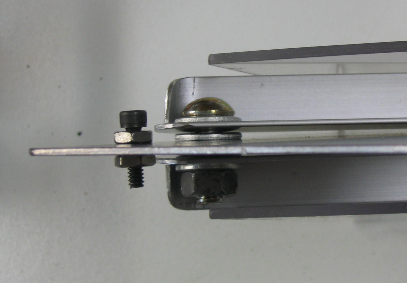
Arms
The cover is attached to the splitter by a pivoting support arm. I made this out of two pieces of aluminum L-shaped track, one on each side of the splitter. There is a hole where they connect to the splitter, and another hole where they connect to the cover. The best way to ensure that the holes line up is to drill them at the same time.
After I drilled the holes, I inserted screws with washers and locknuts to connect the arms to the blade cover and splitter. Since the cover screw goes through the sides of the cover, it needs some extra spacers to hold the arms in the center. I used two short pieces of 1/4″ plastic pipe.
Occaisionally you may want to flip back the cover without removing the splitter. I added a stop screw to keep the arms from flipping all the way over and blocking the wood path on the back side.
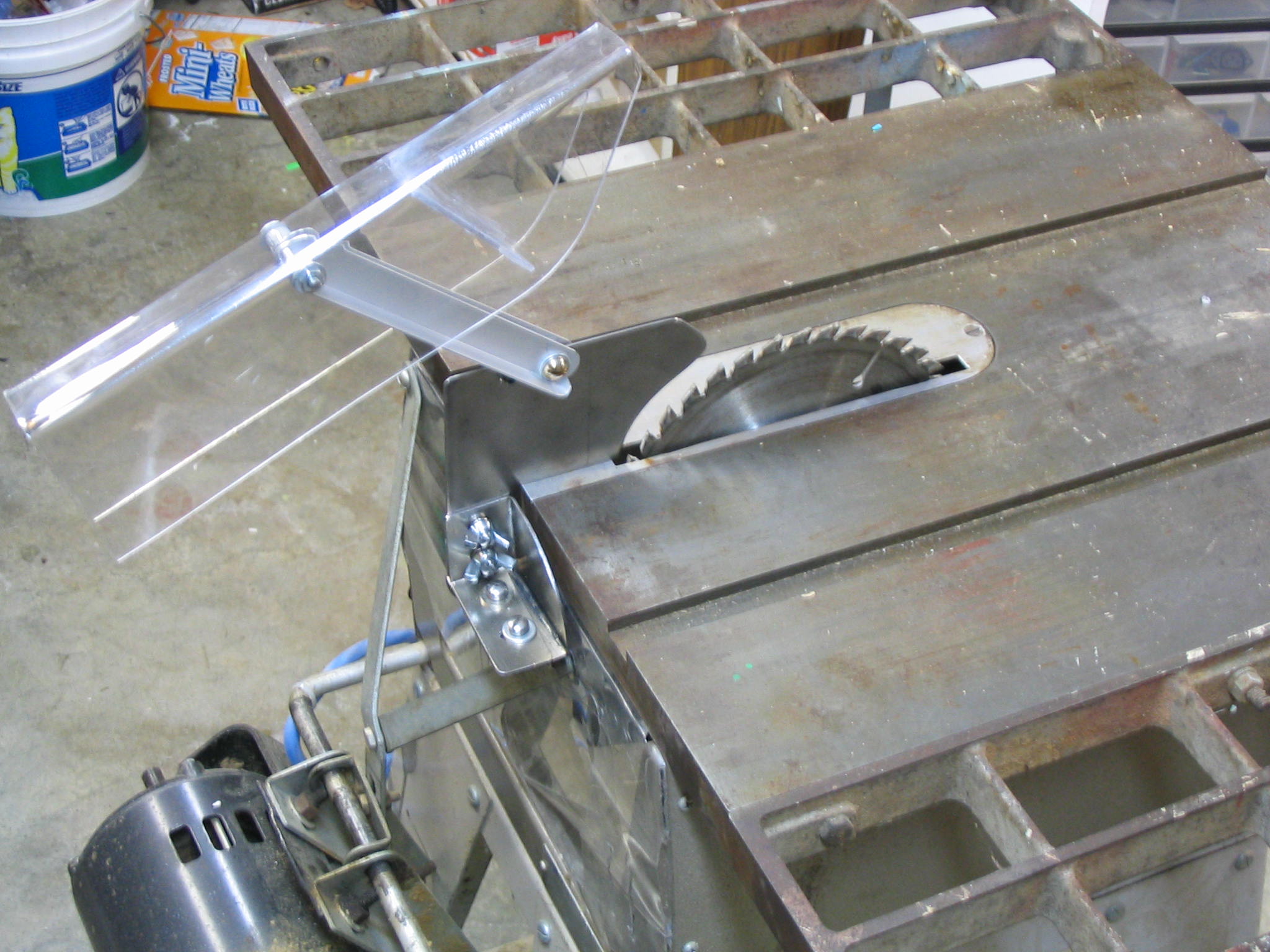
Done
That completes the blade guard.
Powr-Kraft Table Saw
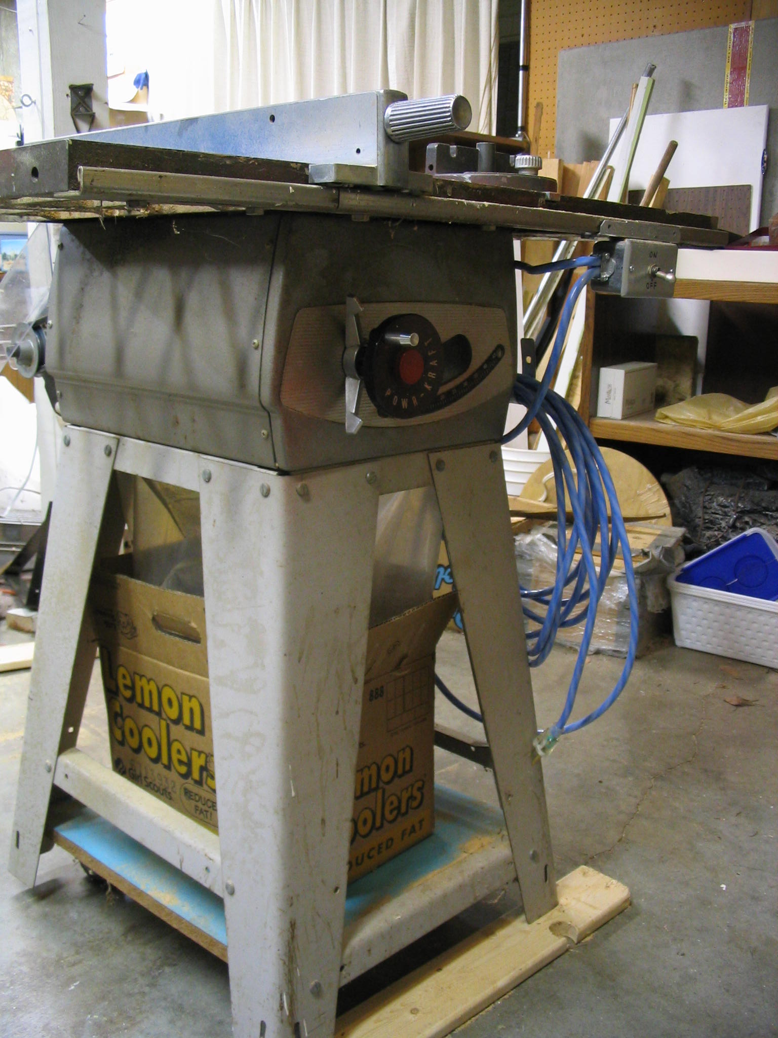
I acquired a table saw last summer at a local estate sale for $20. It needed some repair, but looked like it was likely still in fairly good condition.
The label identifies it as a Powr-Kraft model TMG-3332A from Montgomery-Wards; date unkown. Looking at it, I guessed it was from the 1960s.
The saw takes an 8-inch blade, and is belt-driven with the motor mounted on the back of the frame. Mine has a 1-horsepower Craftsman electrical motor. I know this is not the original since Craftsman is a Sears brand.
My friend Jerry helped me find more information about this saw from the Old Wood Working Machine’s Powr-Kraft page. They had a reprint of a 1956 Ward’s catalog, and my saw is right inside on the second page.
Even though it is 50 years old, it still works nicely, but there are a number of things this saw needs. The electrical wiring needs repair, and it needs some safety guards. Since it is bordering on being an antique, or at least a collector’s item, I’m making sure that any fixes or modifications are not permanent, so it could be restored to original state if desired in the future.
Blade guard mounting bracket
My used tablesaw came without a splitter/blade guard. This is an important safety item, so I am making one for the saw. The first step was to create a mounting bracket where it could attach.
The Table Saw Book Amazon IndieBound |
Background
A blade guard has two main components. The cover goes over the spinning blade, to prevent the saw operator from getting injured directly on the spinning blade. The cover is usually made of clear plastic nowadays, and it is mounted on the splitter. The splitter is a vertical piece of sheet metal sitting behind the blade, which guides the cut wood past the blade so it won’t bind.
The blade on the tablesaw is mounted on a shaft called the arbor. The arbor tilts up to 45 degrees to make angled cuts. The splitter must therefore also tilt along with the blade and arbor to match. The splitter must be aligned perfectly straight behind the blade, so that the cut wood does not bind against it.
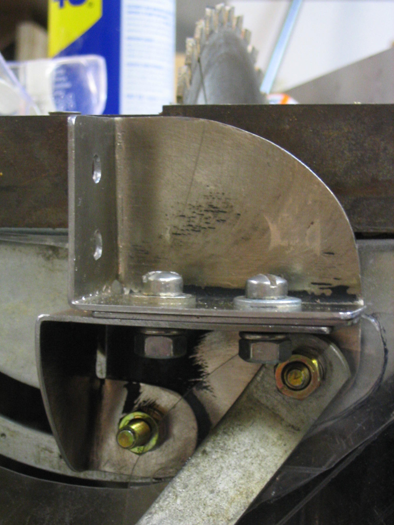
Attachment
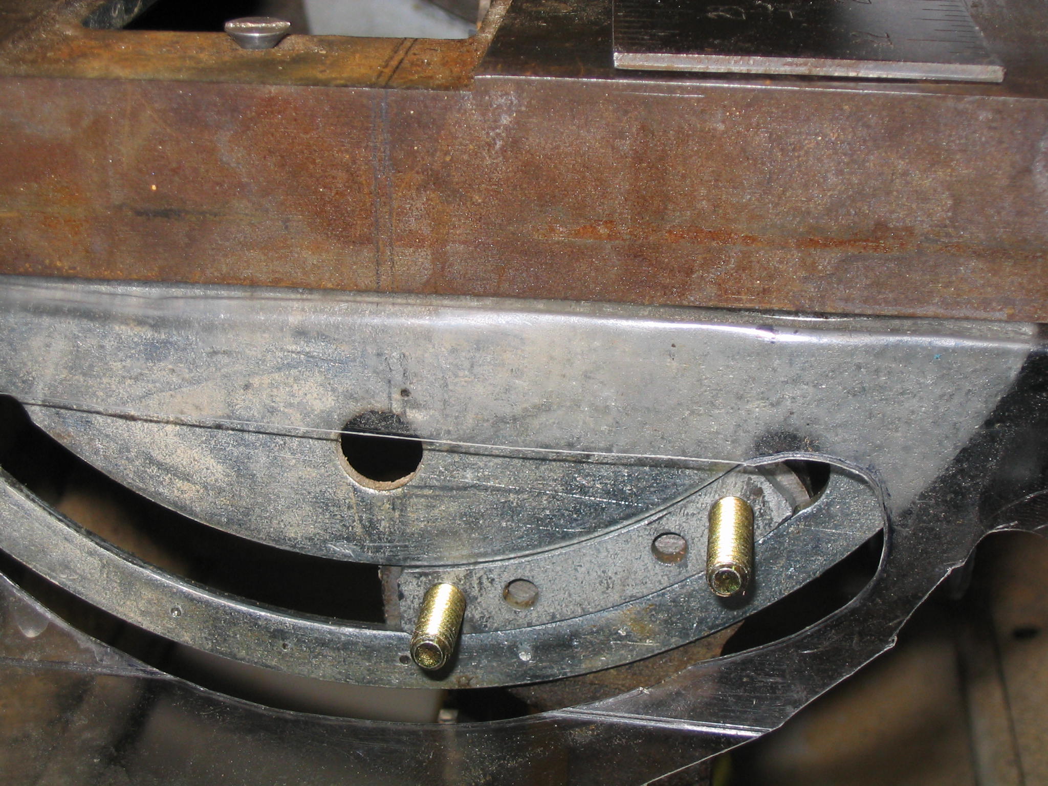
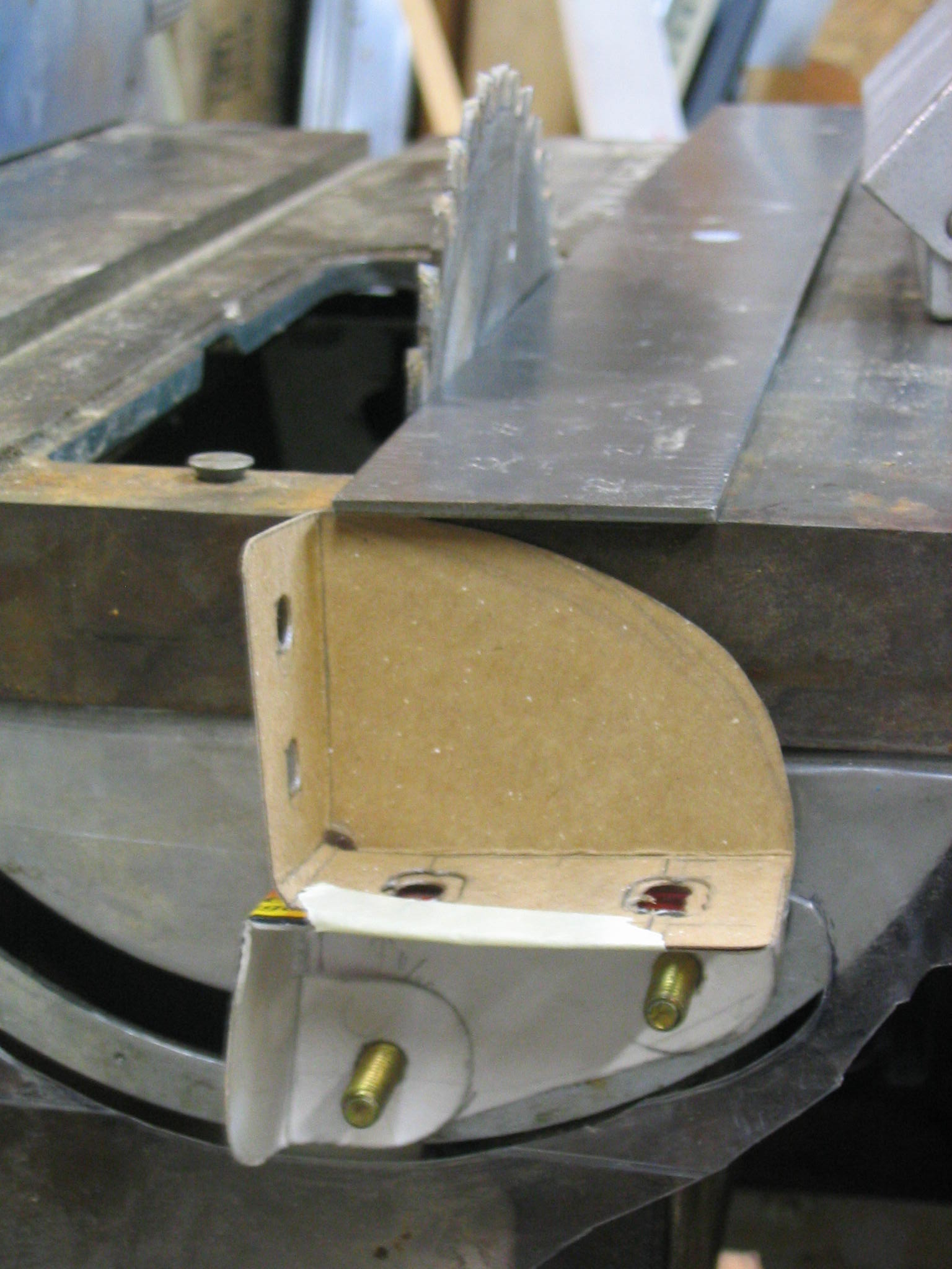
This presents an interesting challenge on a saw that did not come with an obvious mount for a guard. On my saw, the front and rear mounts of the arbor assembly, known as the trunions, slide in curved slots on the table saw frame. The bolts that hold the rear trunion in the slot look like they are the best place to attach a guard. I found a picture of my saw in an old 1956 Ward’s tool catalog, and it appears that the original (optional) guard attached to the back, presumably to the trunion bolts.
For the best adjustability, I am making a two-part bracket to attach to the trunion bolts. The two-piece design allows it to be adjusted in multiple directions and angles. The splitter will attach to this bracket.
Bracket Design
The choice of materials and construction methods affect the design. The guard must be mounted so that the splitter is aligned with the blade. I am making the guard out of materials I have on hand, and I don’t have precision metal fabrication tools. Therefore, adjustability is a major component of the guard design.
I am making the splitter and mounting bracket out of heavy sheet metal. The standard table saw blade width (“kerf”) is 1/8″, so the splitter must be thinner than that.
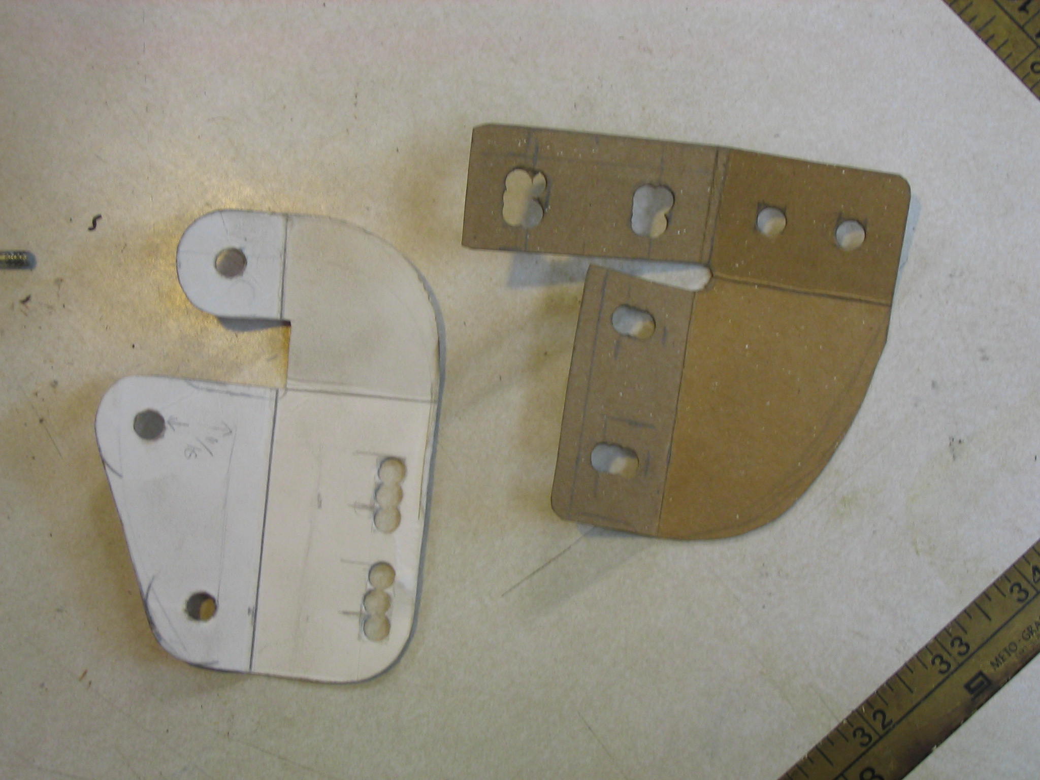
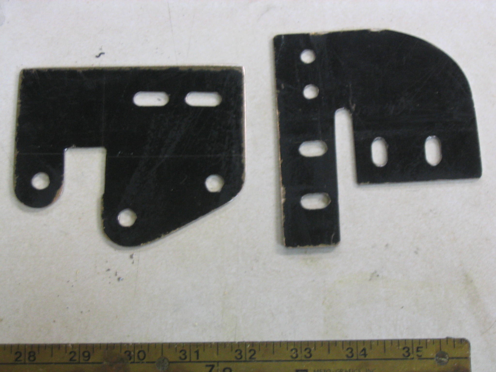
I first made some templates out of carboard, allowing me to adjust the size and positioning, before cutting any sheet metal.
Metalwork
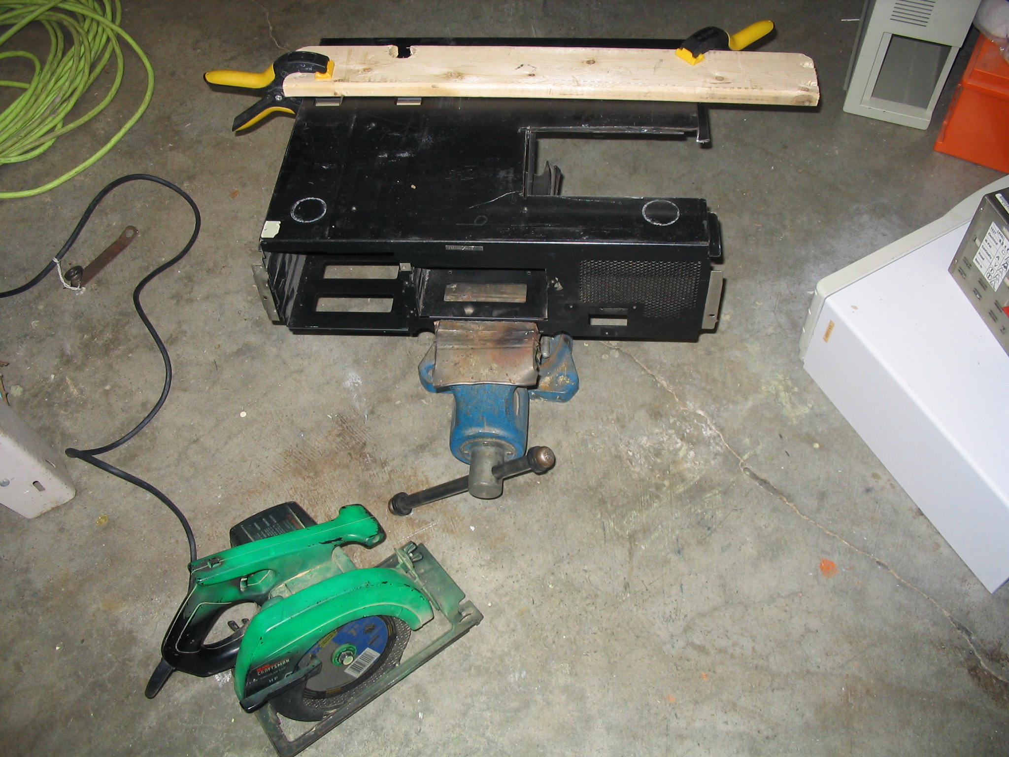
I have salvaged the sheet metal from the base of a personal computer case. This one was a genuine IBM AT 286 case, and the metal is about 1/16″ thick (1.6 mm). This heavy metal can take a while to cut with a hacksaw, so I made the rough cuts with a metal-cutting blade on my circular saw. The metal cutting blade is basically a thin grinding wheel, which spits lots of sparks and fireworks. Keep anything flammable well away from your cutting area. The metal PC case was slippery, so I clamped a wooden board down as a saw guide. The circular saw made quick work of it, and the blade was only a few dollars at the local home improvement store. If you don’t have a circular saw, a hacksaw will still work.
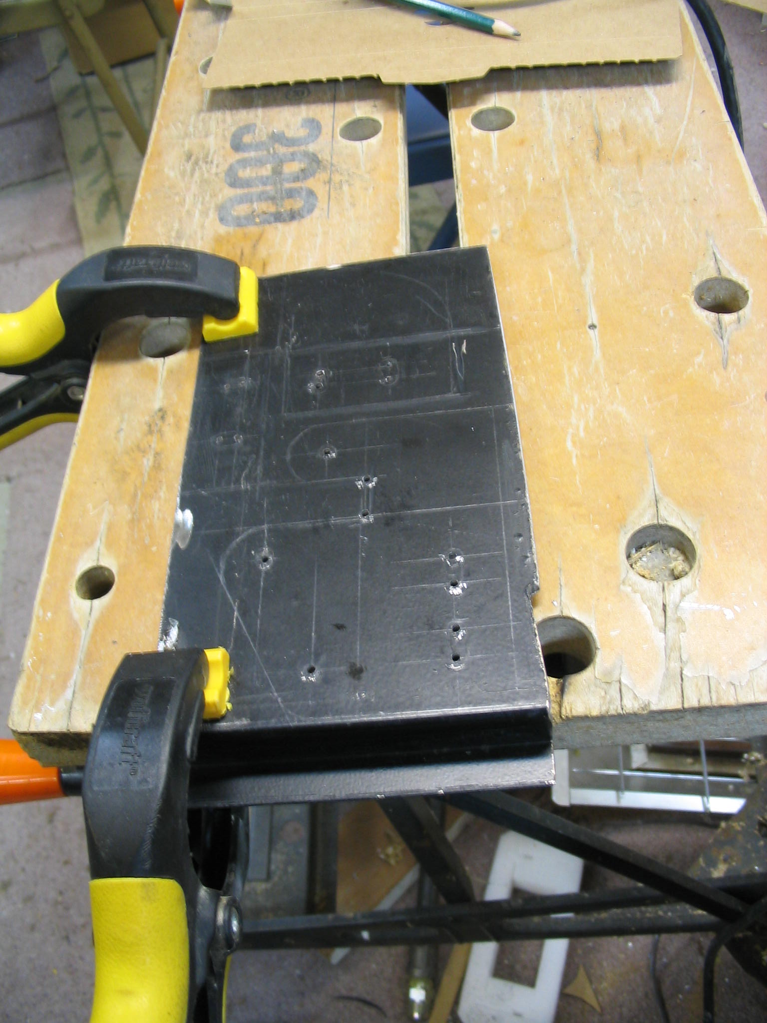
After cutting out a rough blank piece and filing the burrs off, I transferred my cardboard template onto the metal.
The trunion bolts are 1/4″ diameter (6 mm), so I’m using the same size on the rest of the holes and bolts. When drilling holes in metal like this, the drill bit can drift easily and the hole can end up in the wrong place. To avoid this, use a hammer and center-punch to make a dimple where you want the center of the hole. If you don’t have a center punch, pound a sharp deck screw with a hammer as a substitute punch. Then drill a pilot hole the center with a small bit, say 1/16″ or 3/32″. Then your larger bit will stay in proper place for the actual hole.
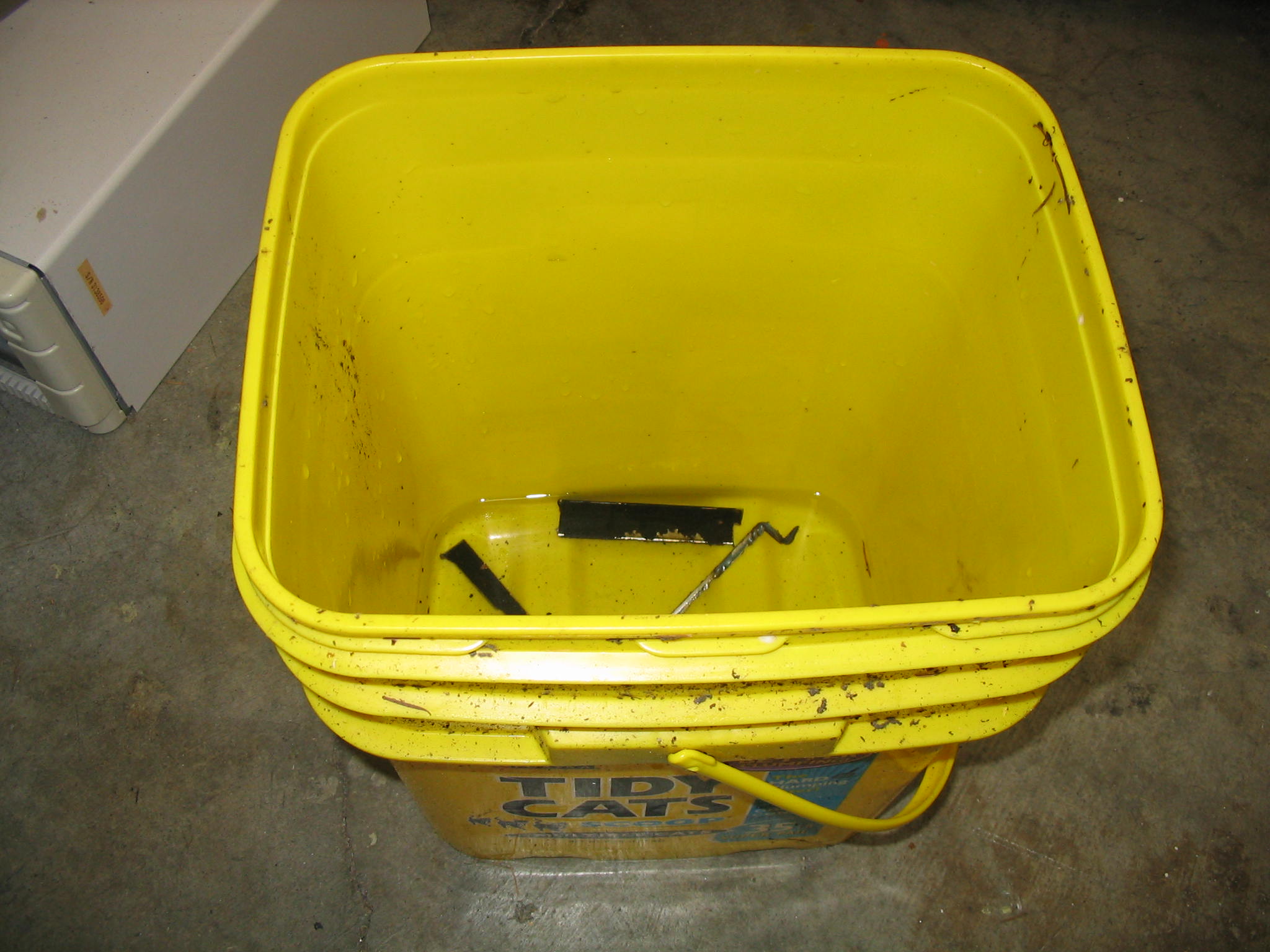
I used the circular saw to make the rough cuts of the brackets. The cutting wheel heats the metal scraps enough to burn you. Use pliers to pick up any scraps, and drop them in a bucket of water.
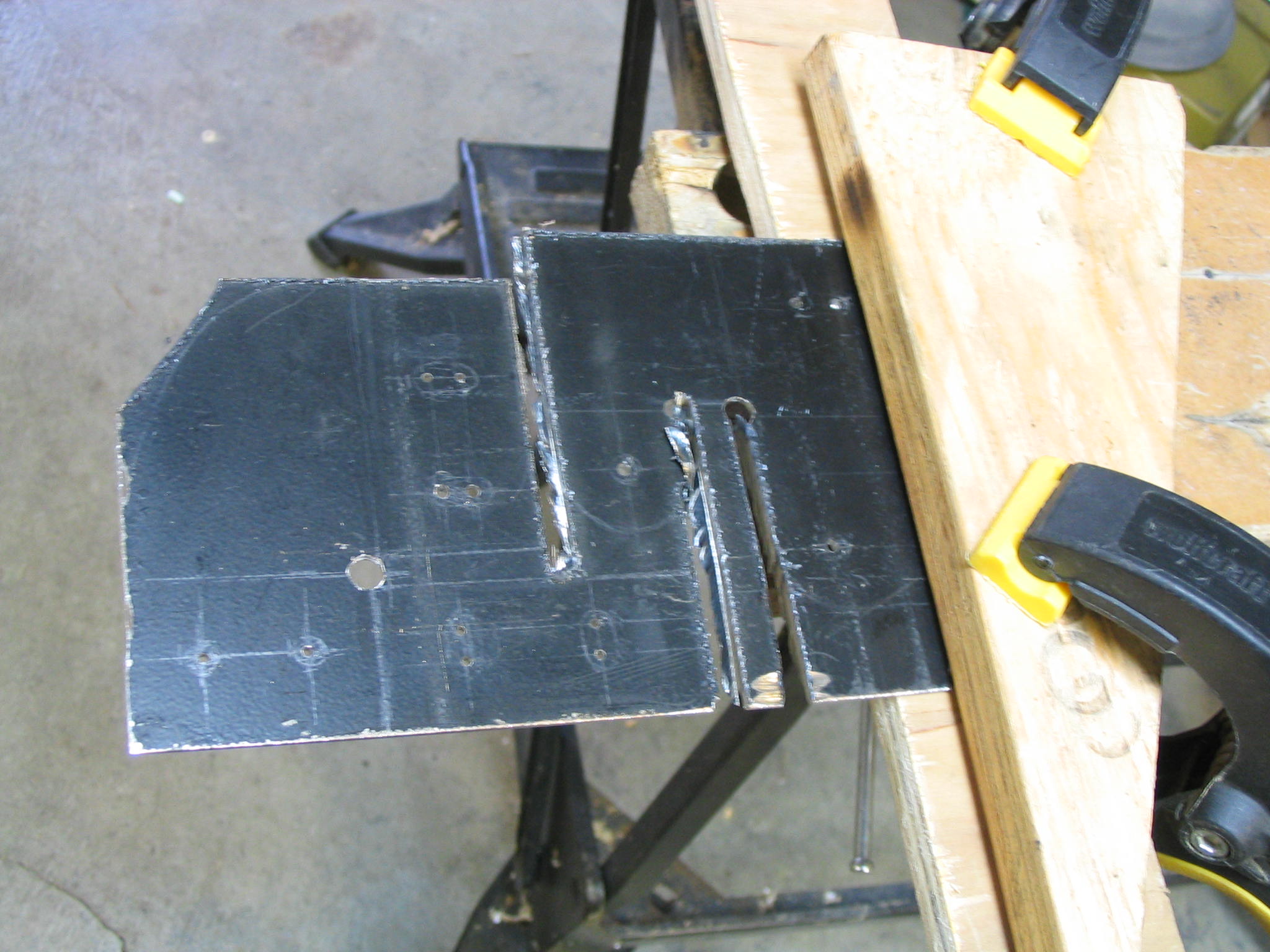
Once the brackets are rough cut, finish any remaining cuts with a hacksaw, and file all of the edges smooth.
Bending
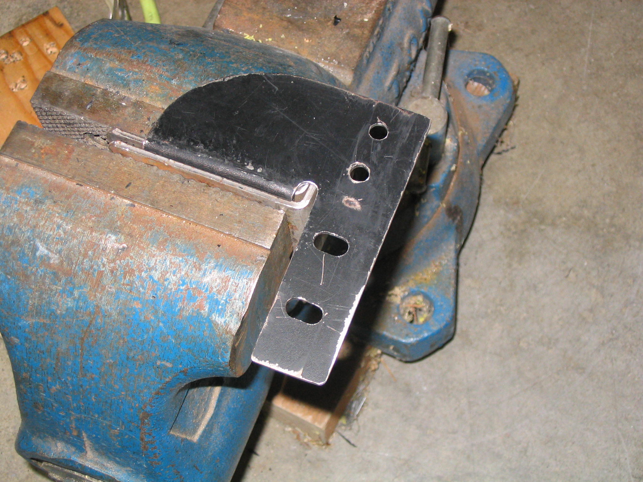
After the bracket pieces are filed to shape, they are ready to be bent. The ideal way to bend them is to use a metal brake, which most people don’t have in their garage. Alternatively, stick them in a vise and pound them with a hammer like I did.
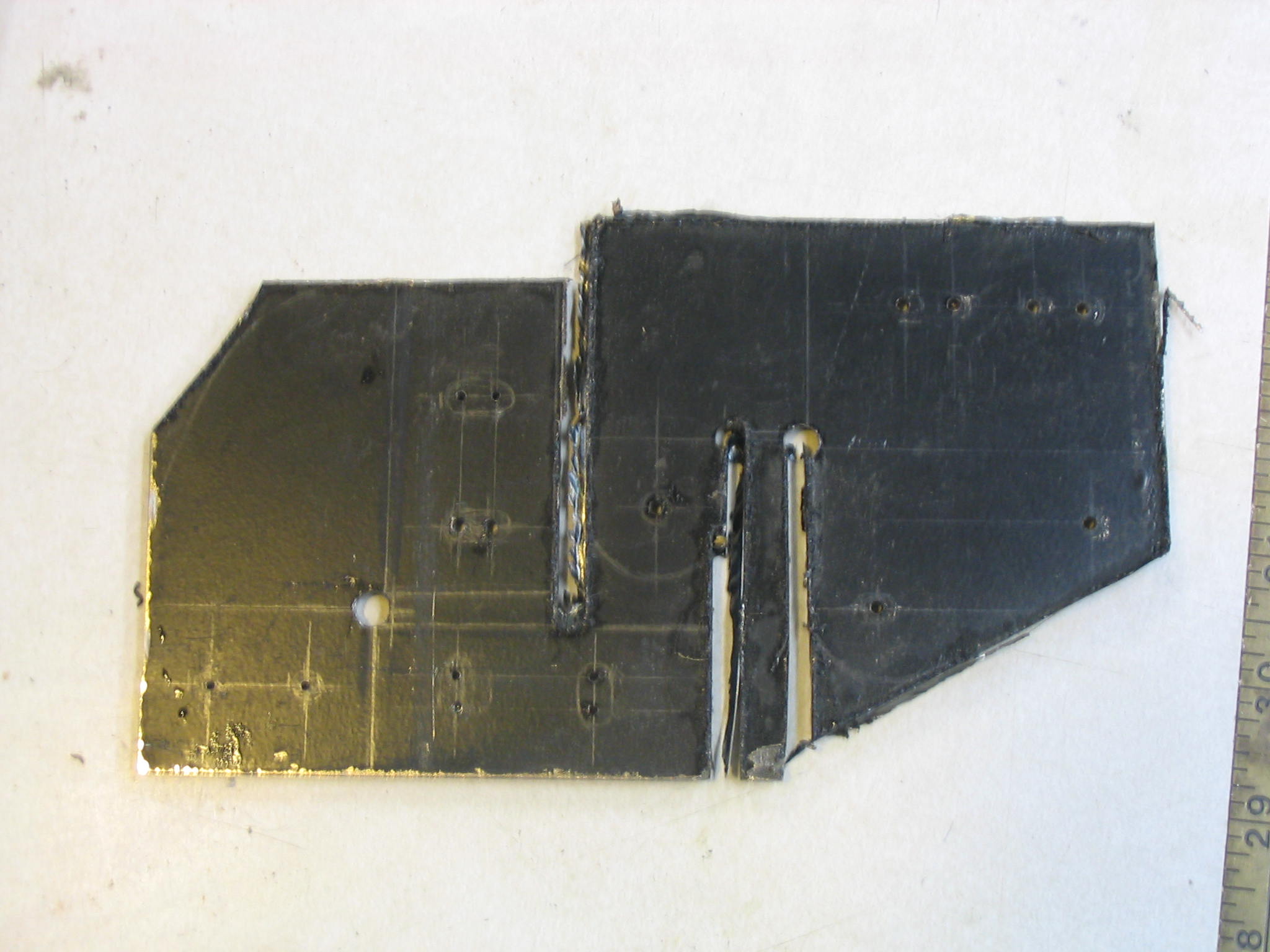
On each bracket, there is an overlapping flange where a bolt goes through. Ideally, you should not drill the hole through the second flange until after the bracket is bent to shape. I had to widen holes on one of the brackets because my bends weren’t aligned perfectly.
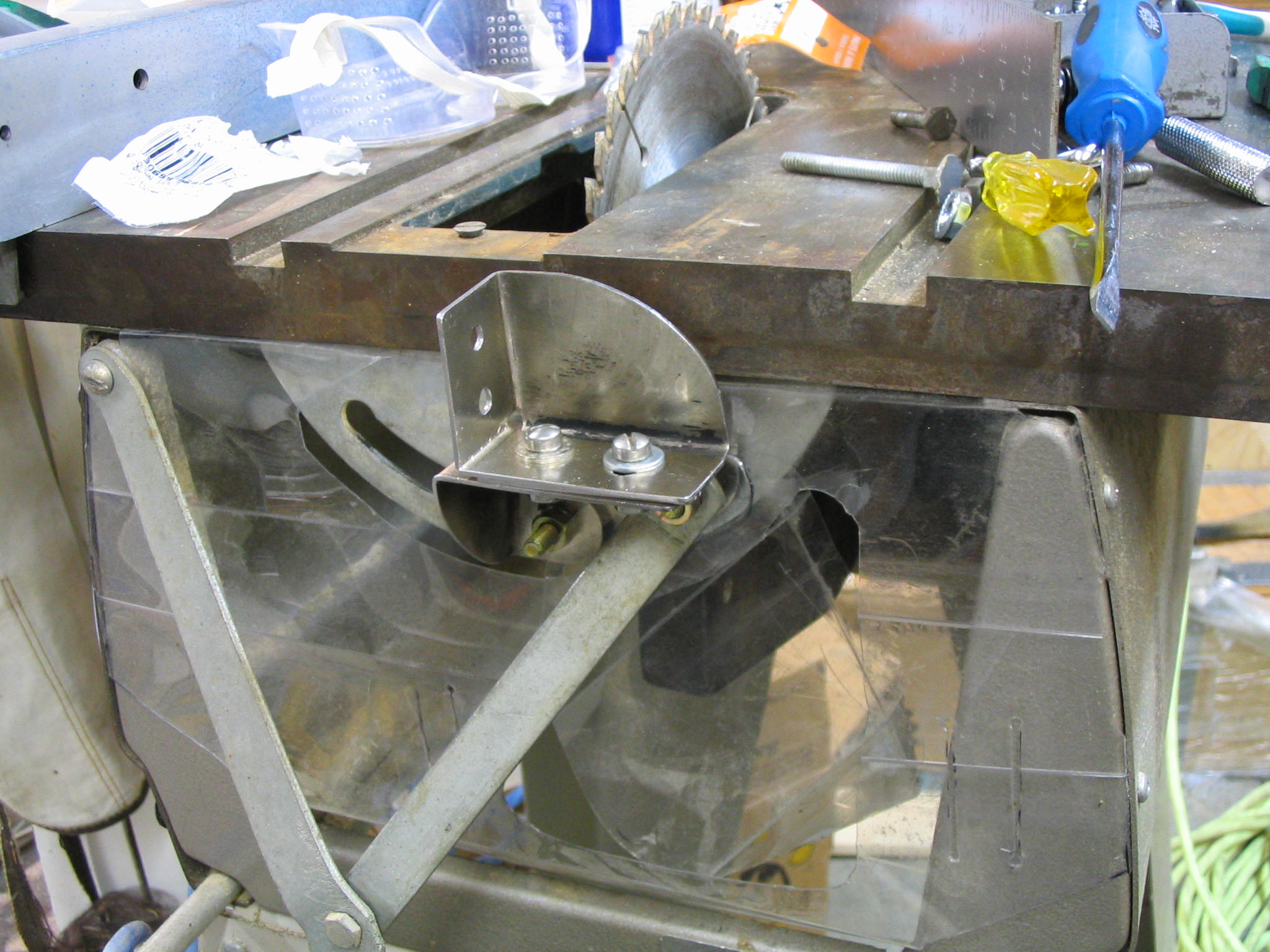
Finished bracket
Once the bracket pieces are bent, they are ready to be attached to the table. I used split-ring lock washers on each of the bolts to ensure that they don’t work loose with the vibration of the saw. The mount is now ready for use.