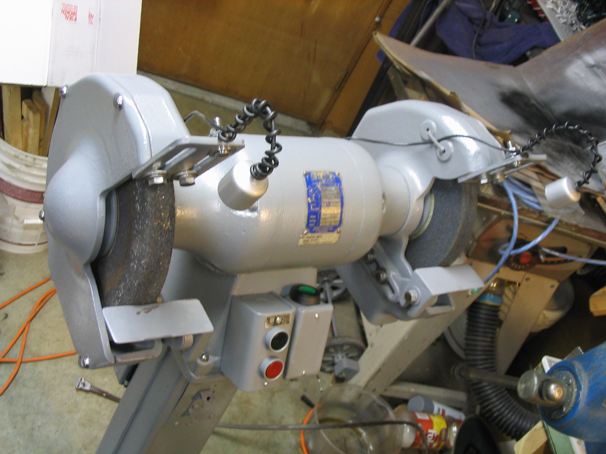
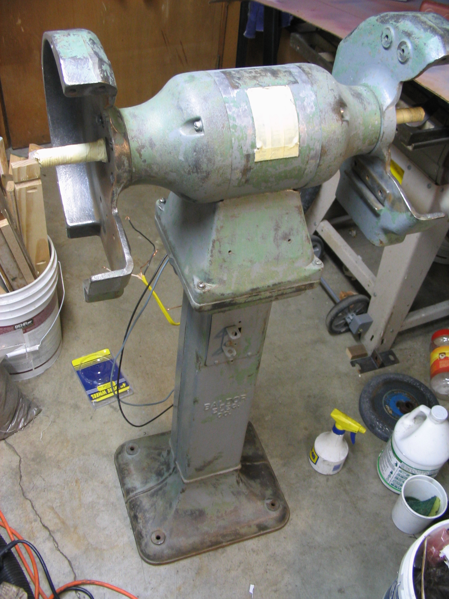
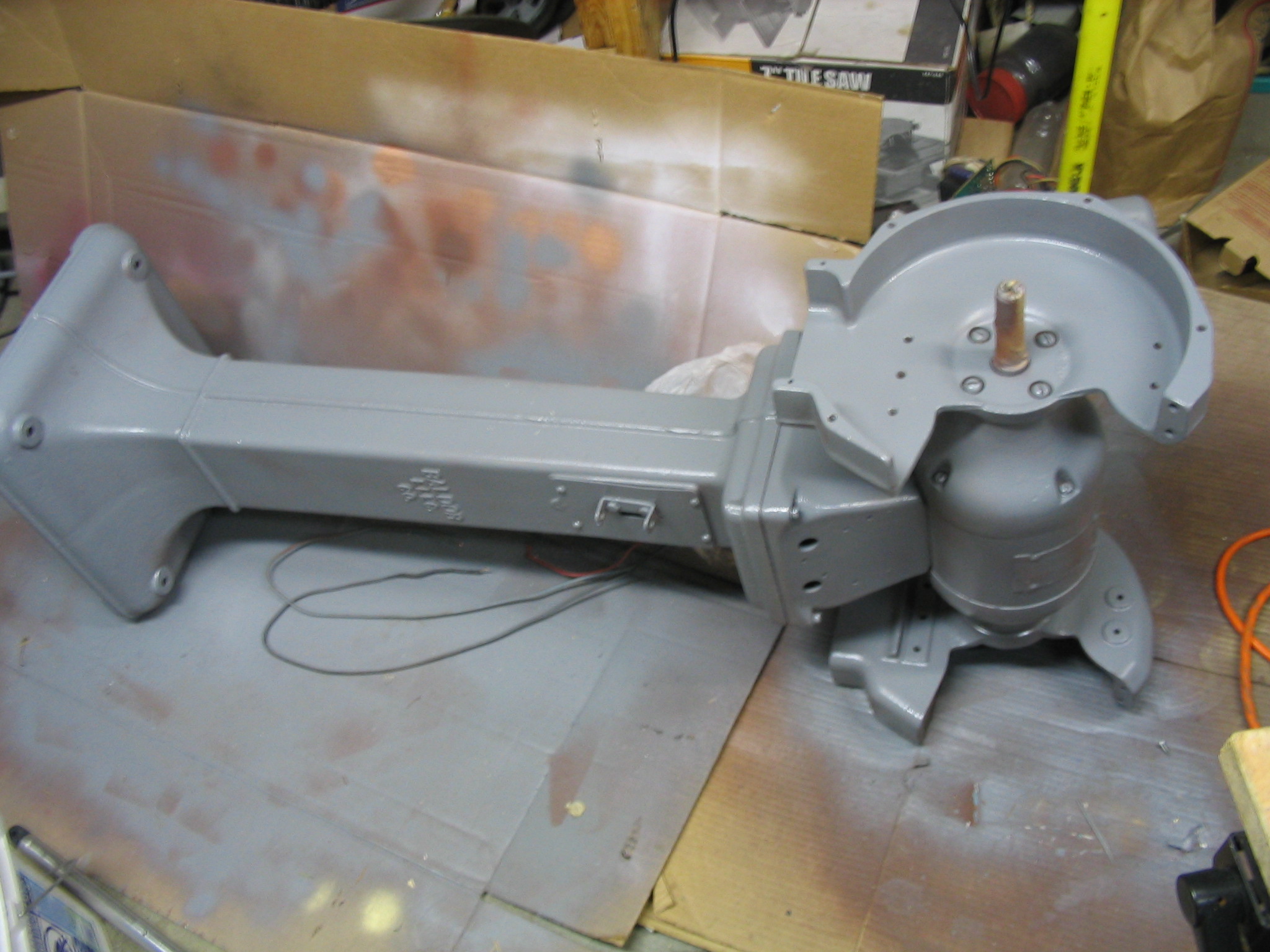
I received a Baldor metal grinder with 10-inch wheels, on its own pedestal floor stand, discarded from a school metal shop program. Several owners before me did not know what to do with it, mainly because the motor is wired for three-phase industrial power which is not found in U.S. residential homes. My job was to fix it up and get it working.
There were two major tasks to the restoration: cleaning/repainting, and making the three-phase motor work.
Cleaning and Painting
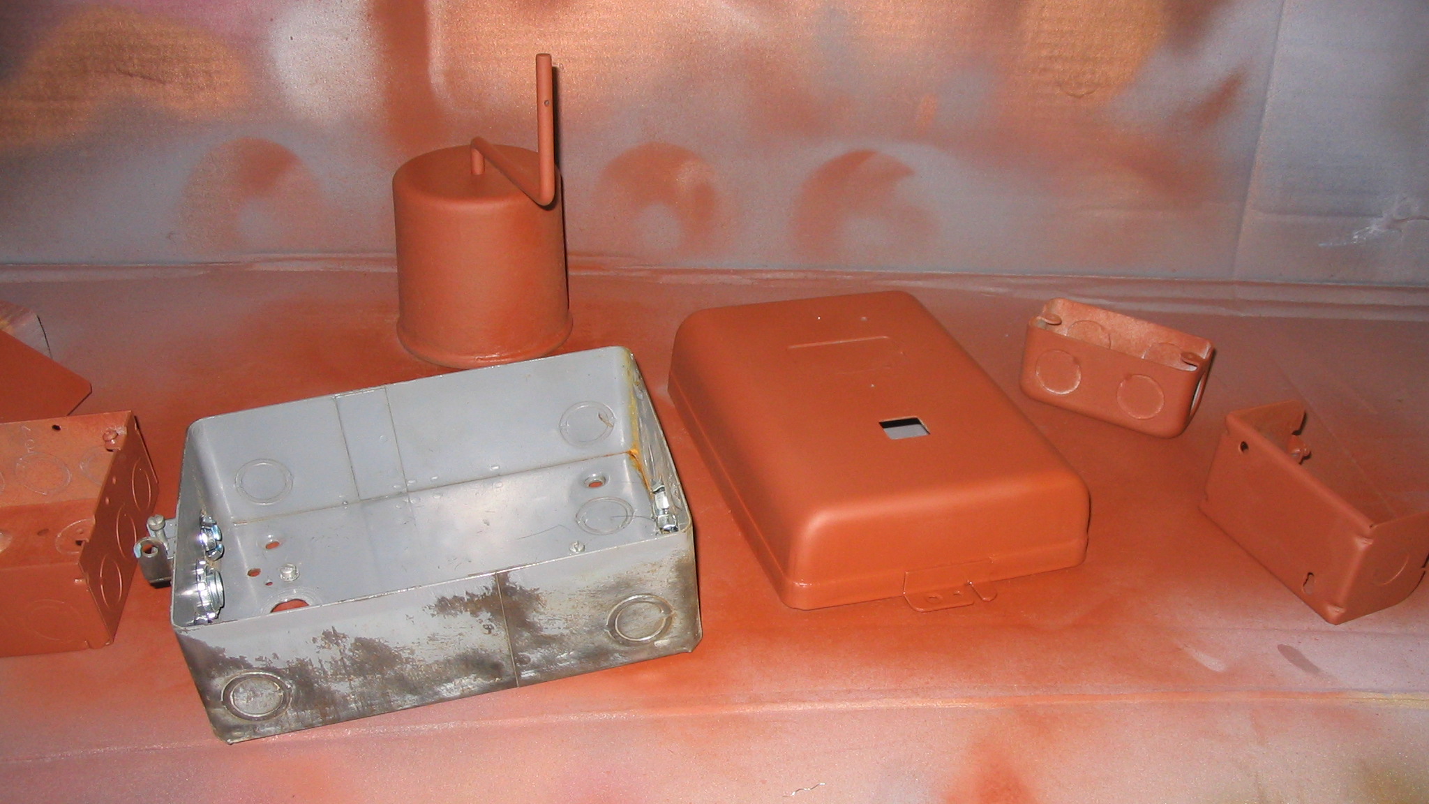
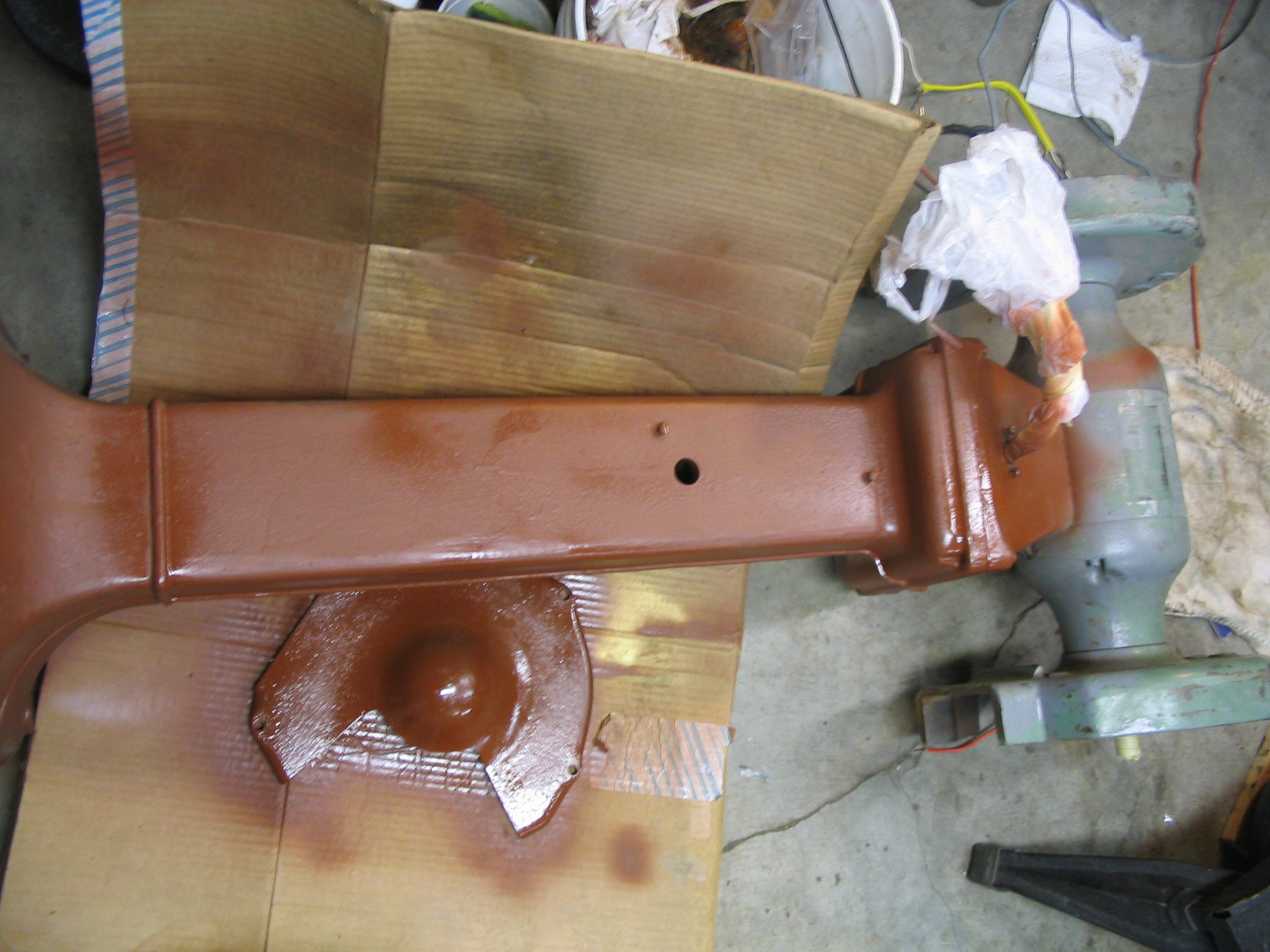
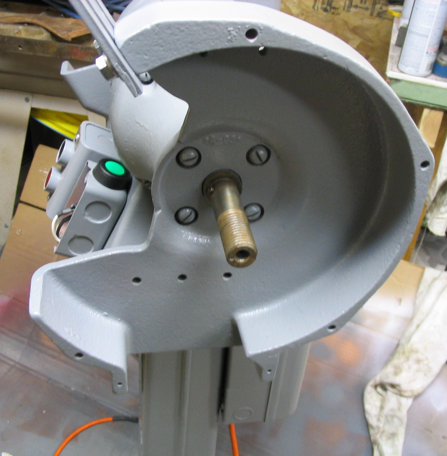
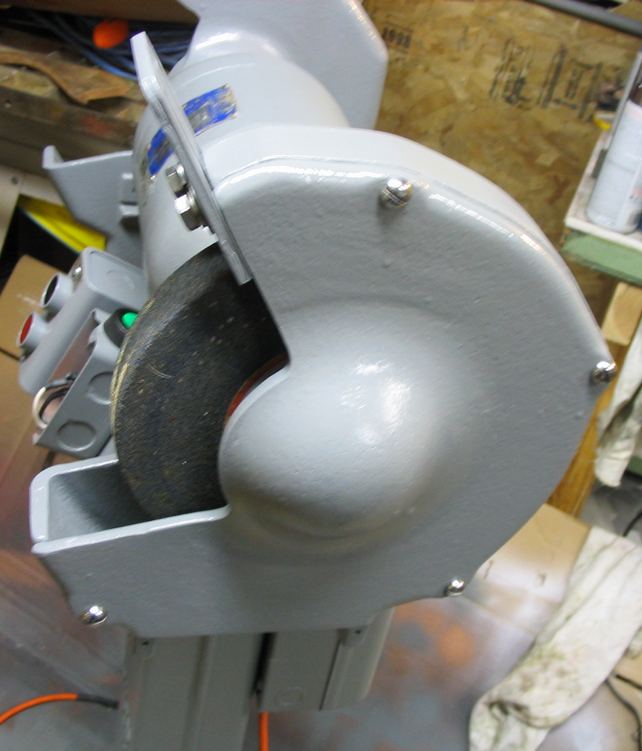
I started the cleaning process by removing all attachments that I could, including the wheel shroud side covers, the wheels themselves, and all electrical boxes and covers. I remove all of the old flaking paint and minor rust spots using a wire wheel brush on the electric drill. Some of the paint was still good, but much of it was stripped down to the bare metal. I could not remove the riveted-on motor label and didn’t want to paint the wheel axles, so I covered them with masking tape.
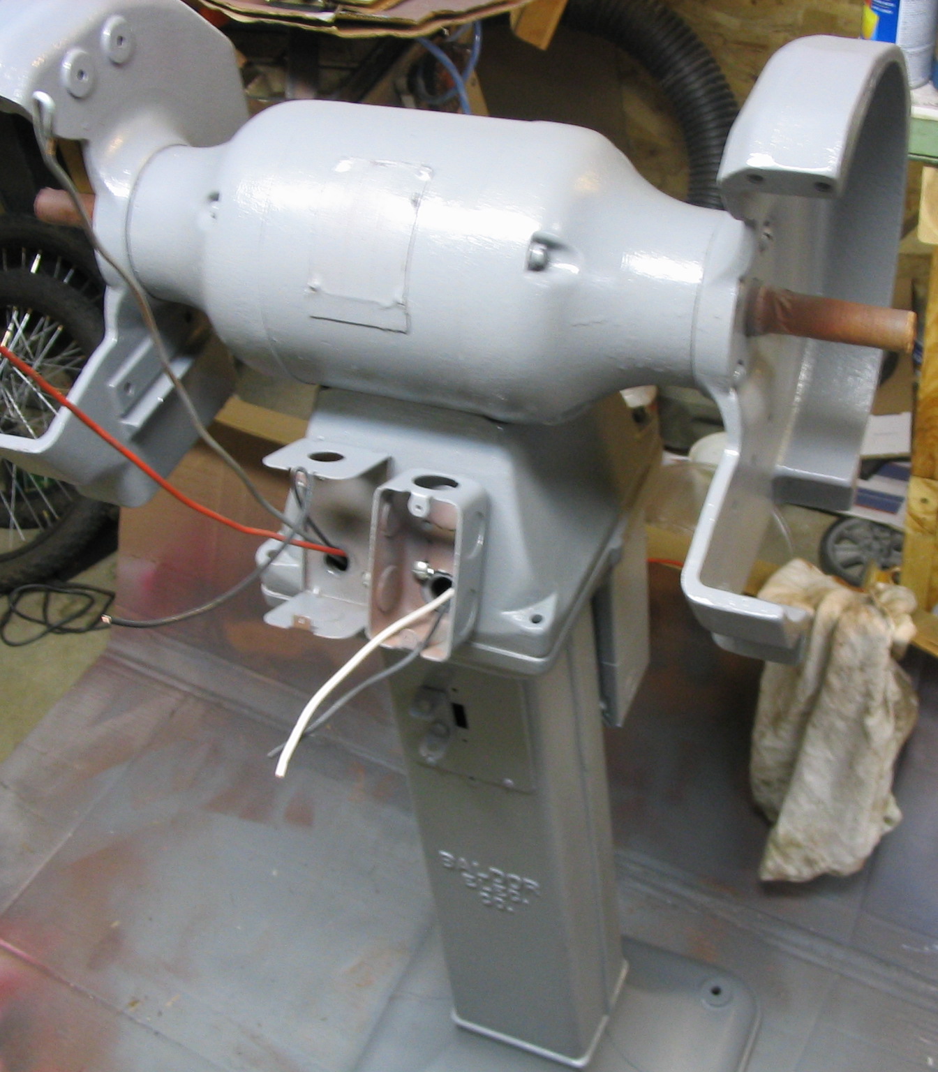
I spray painted the entire grinder and all the separate parts with primer for a good base coat. I followed it with a few coats of grey paint.
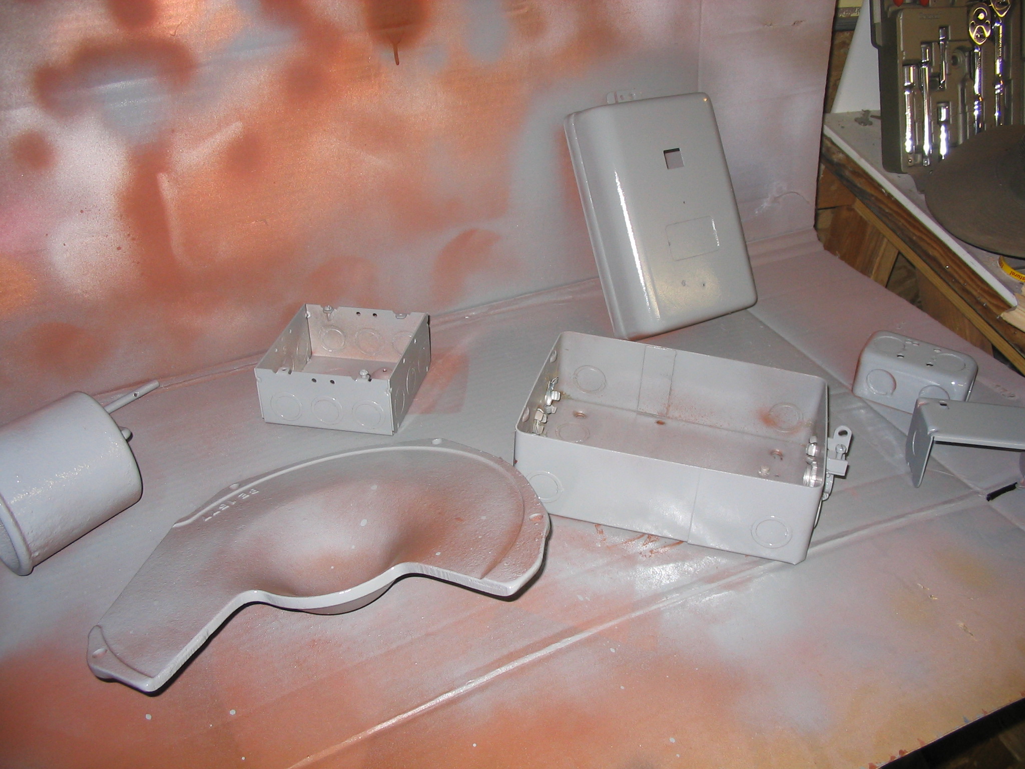
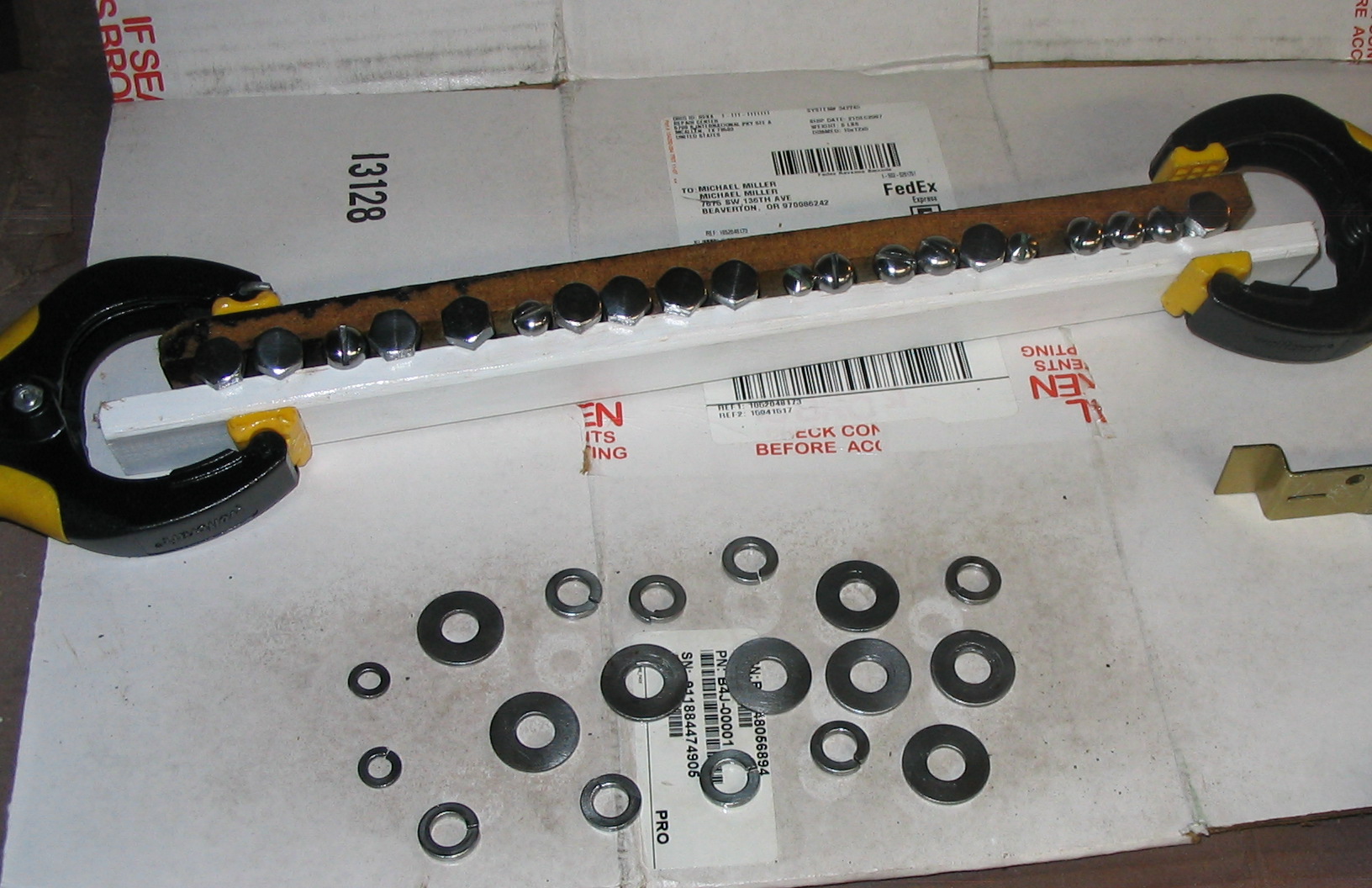
I cleaned up the hardware to make it look a little nicer. I filed and sanded the heads of the screws and bolts while spinning them in the drill press. I buffed all of them with a cloth wheel, which made them nice and shiny. I finished it with some clear spray varnish.
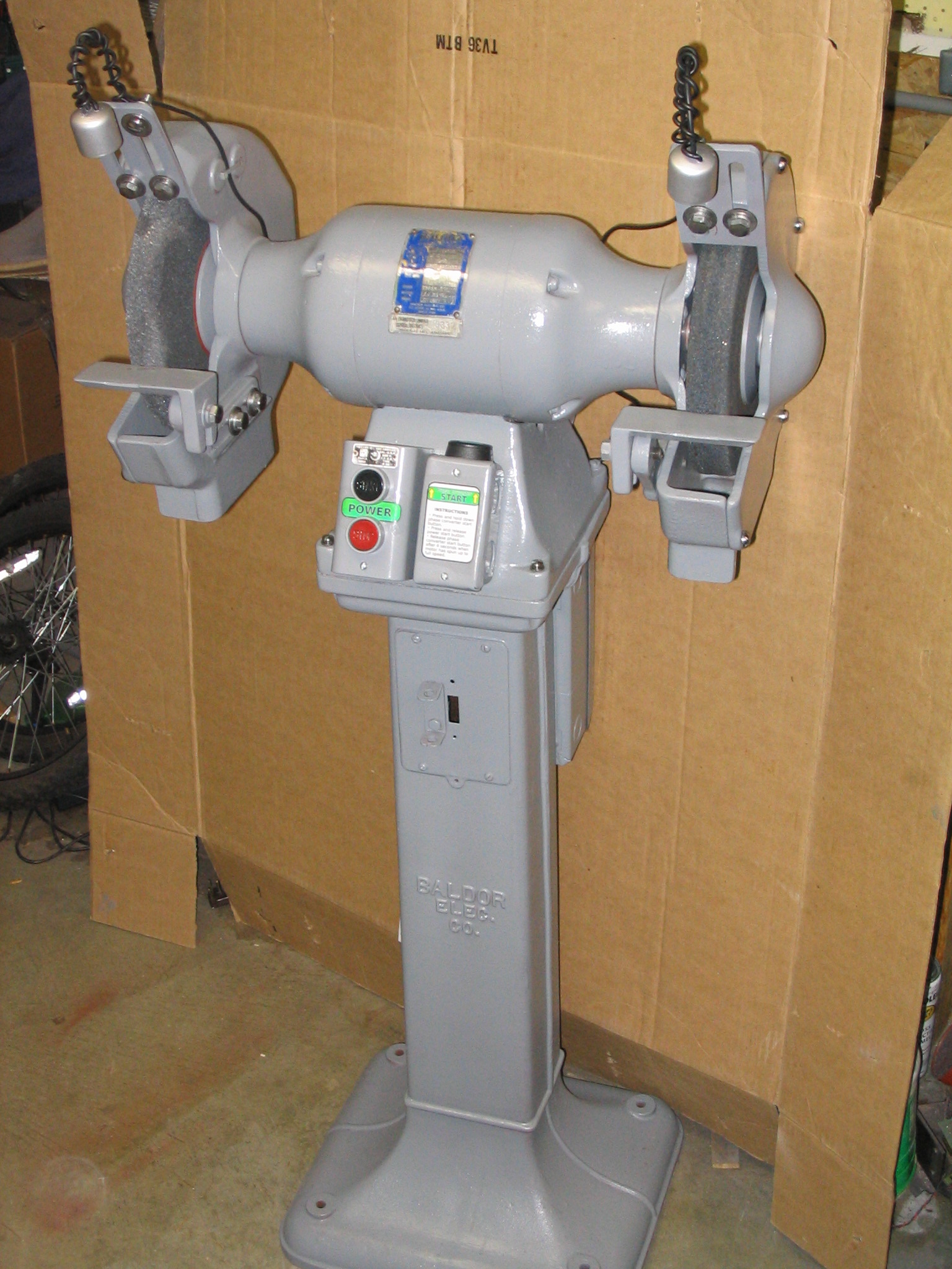
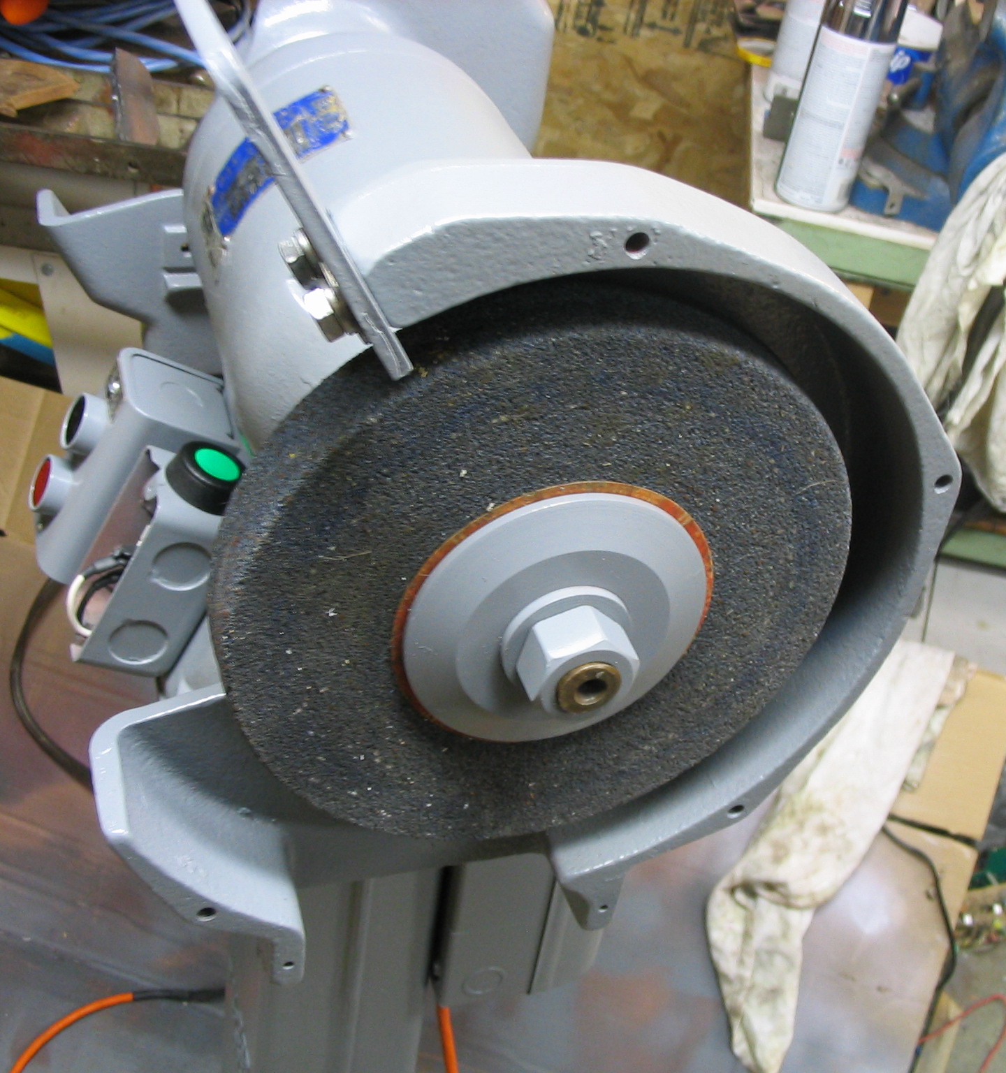
I reassembled all the pieces, back in the order they came off.
Electrical
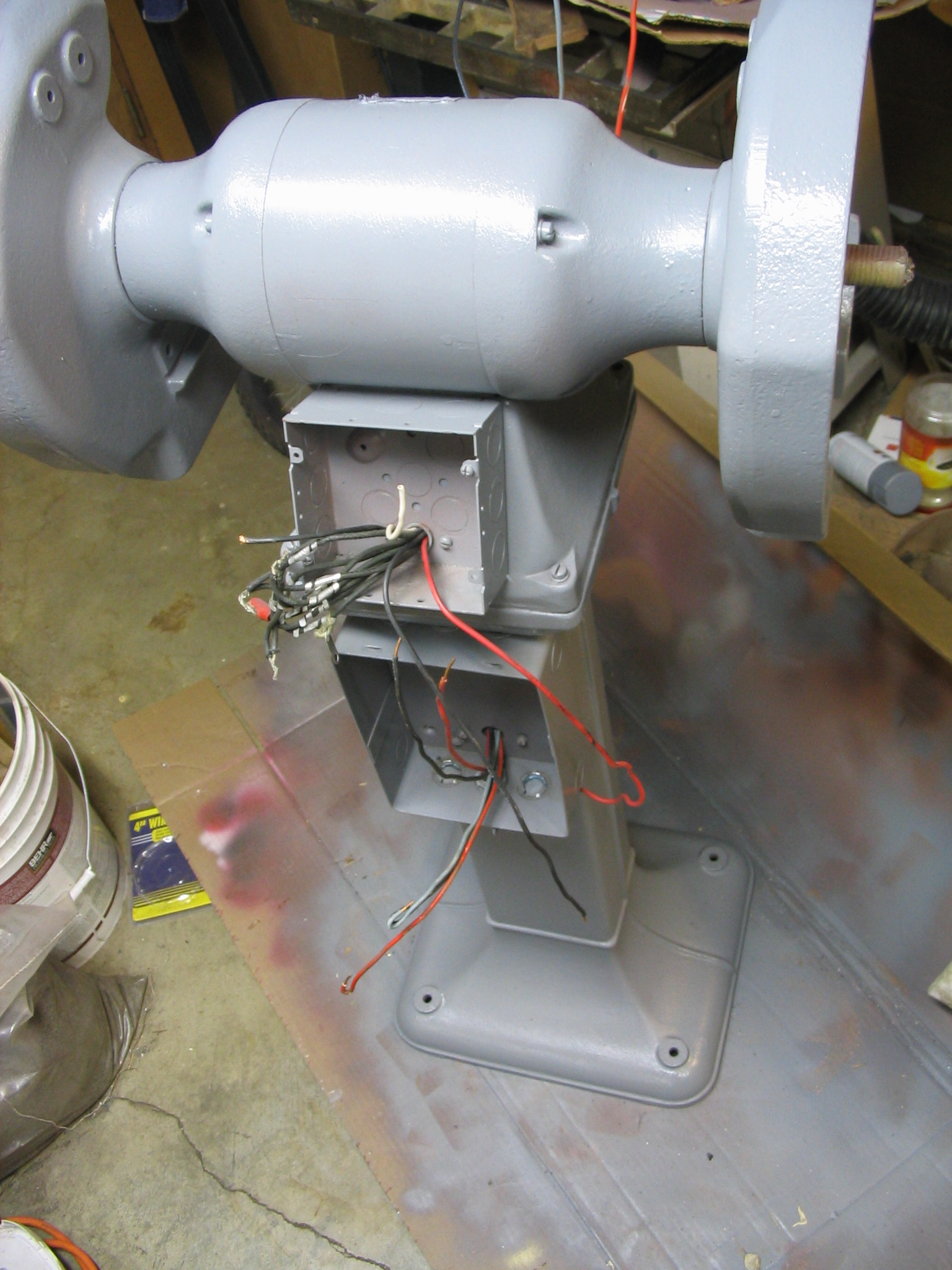
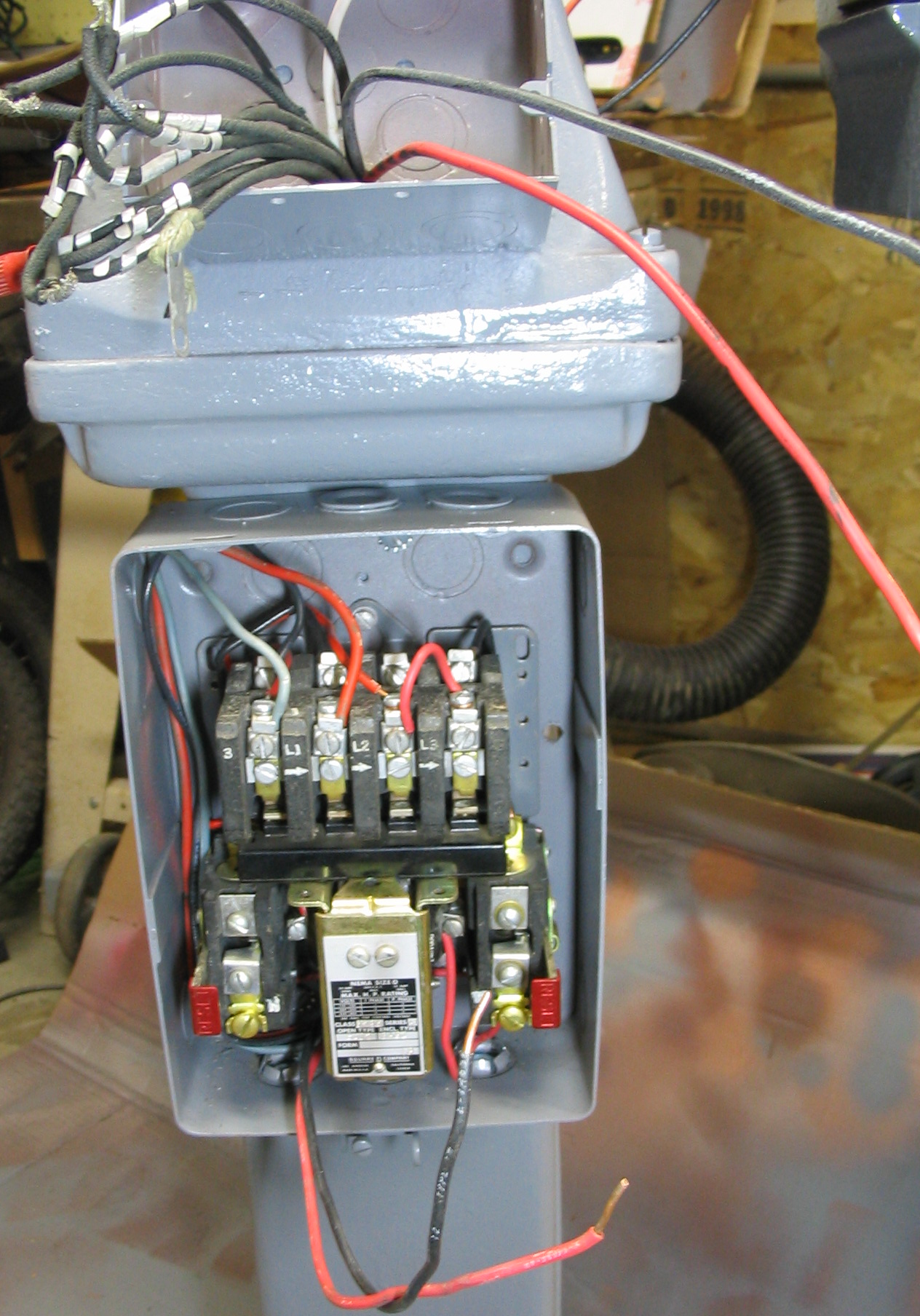
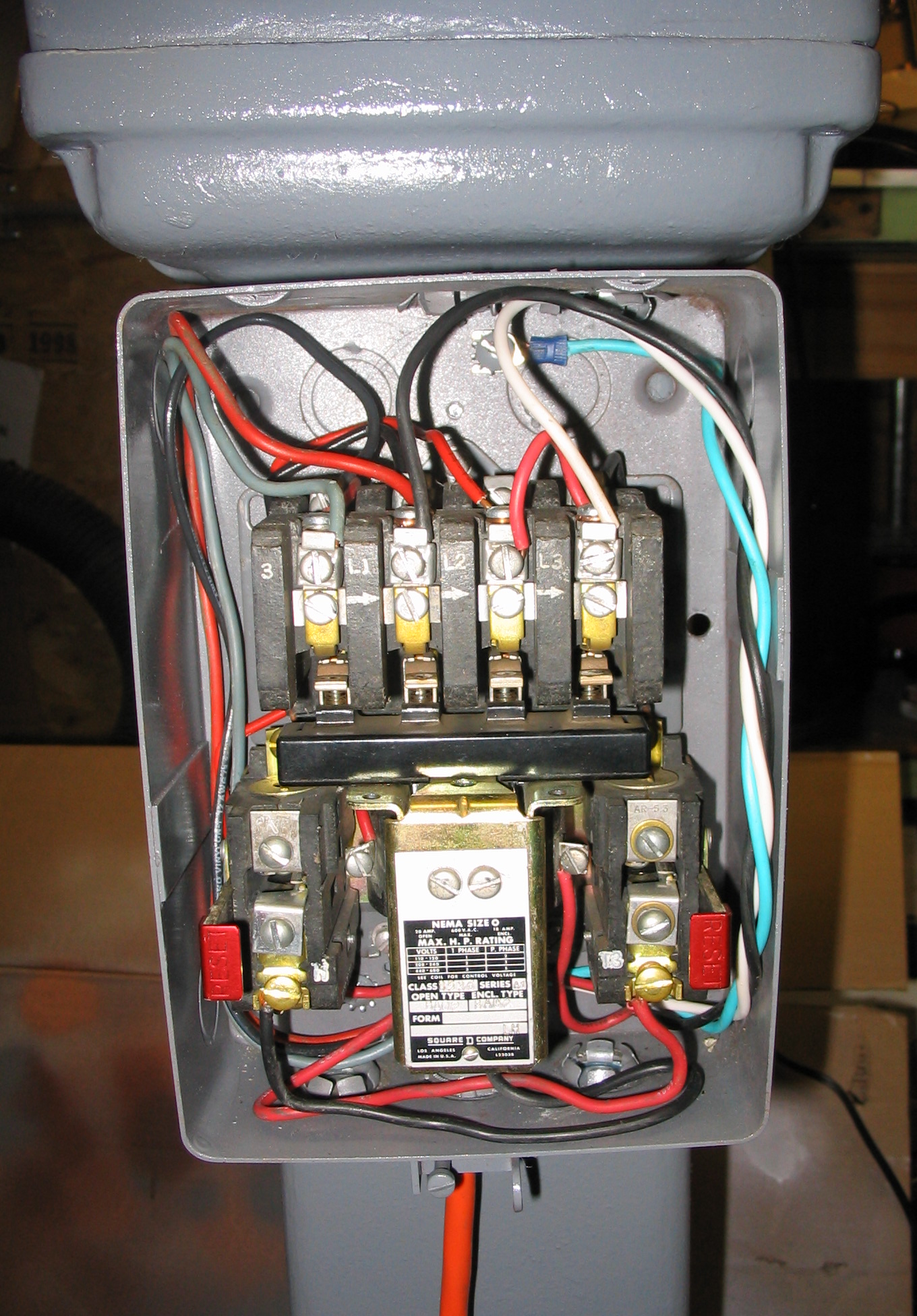
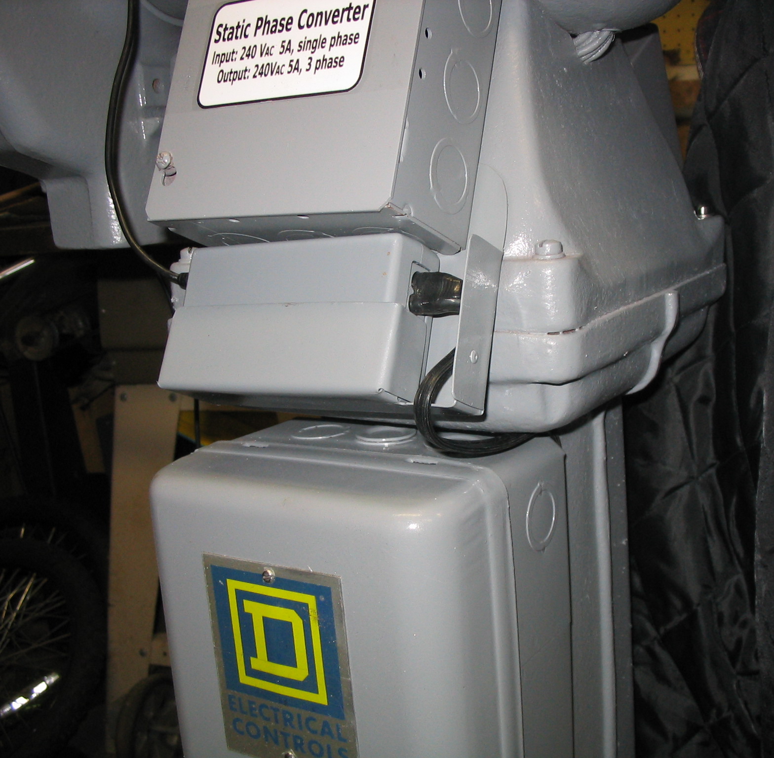
Originally this grinder was hard-wired to the wall using “BX”-style flex conduit. There was a power relay and circuit breaker box, which engaged and disconnected all three phases in sync, using start and stop push buttons.
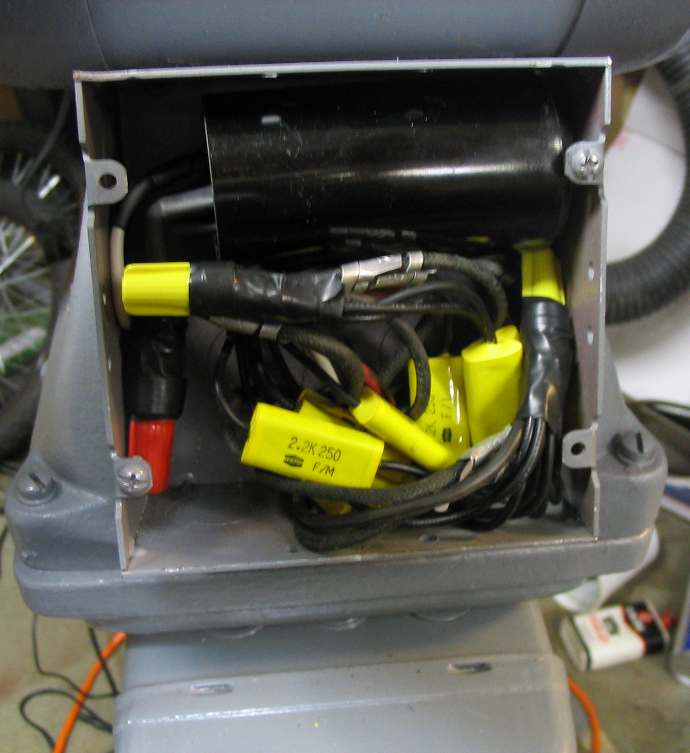
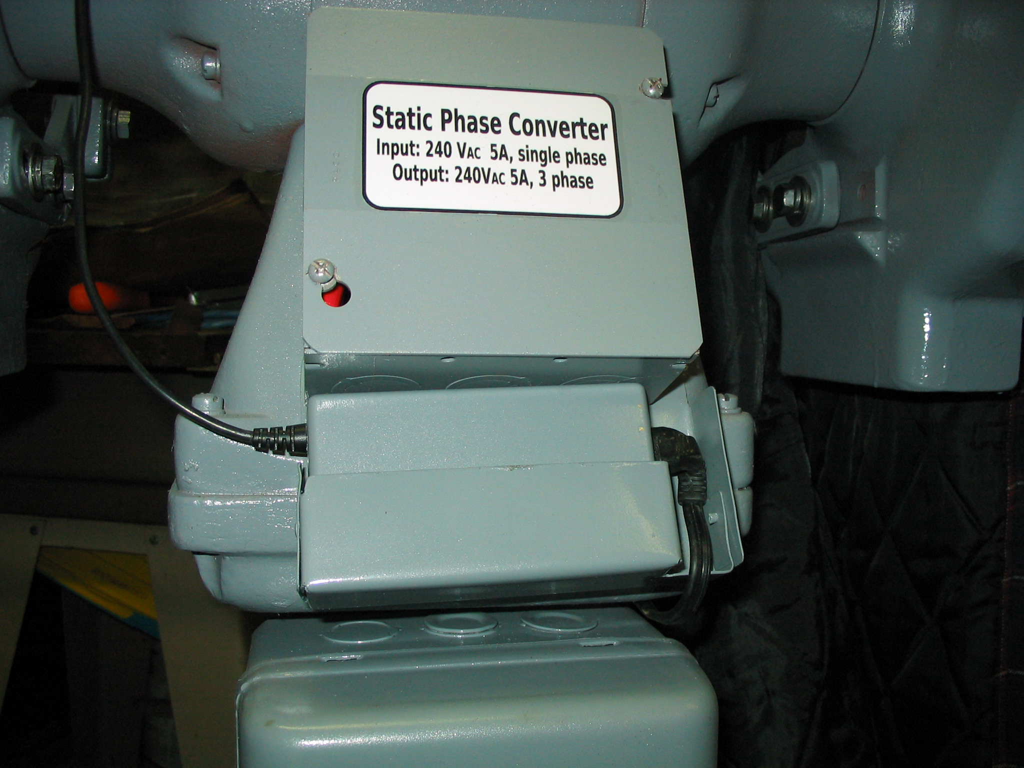
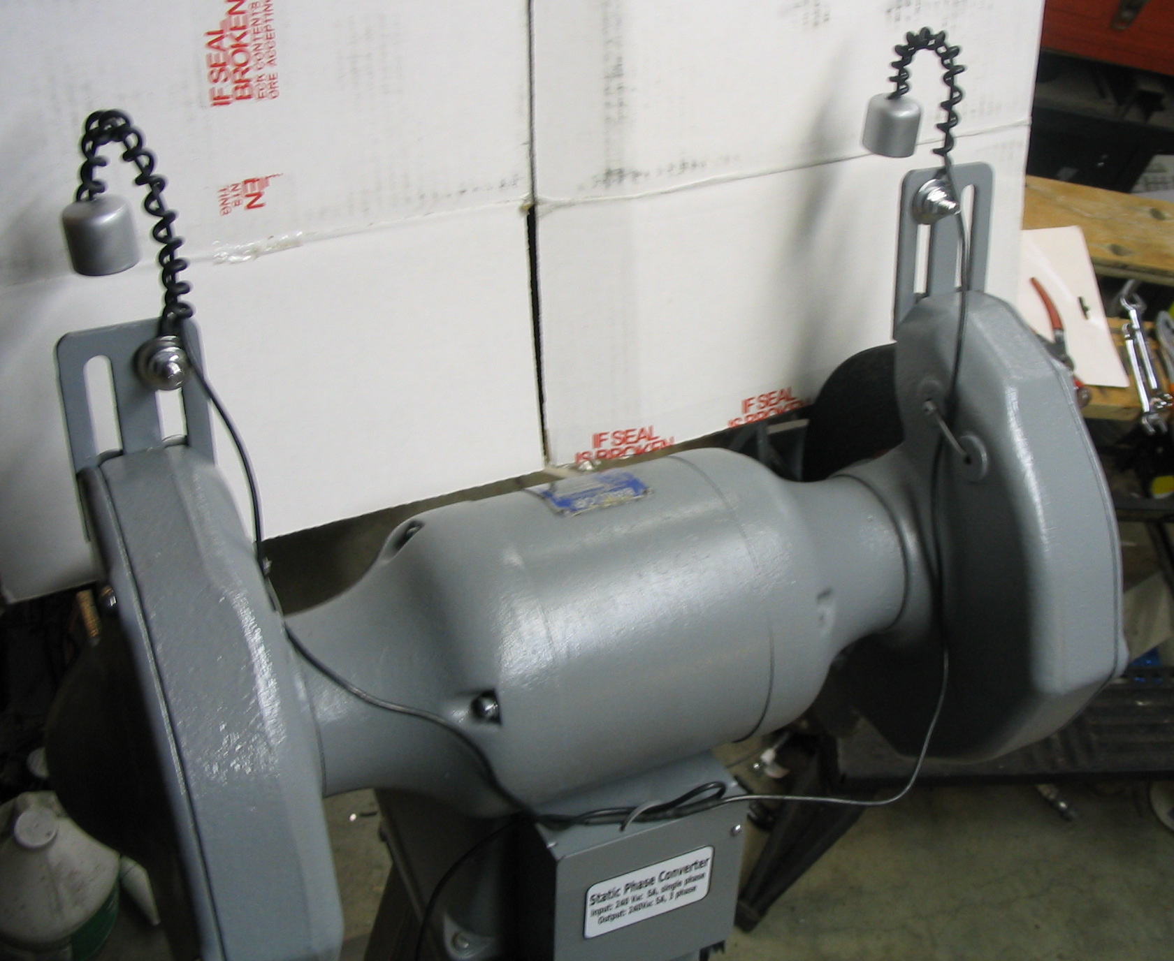
For the 3-phase power, I built a
static phase converter using capacitors.
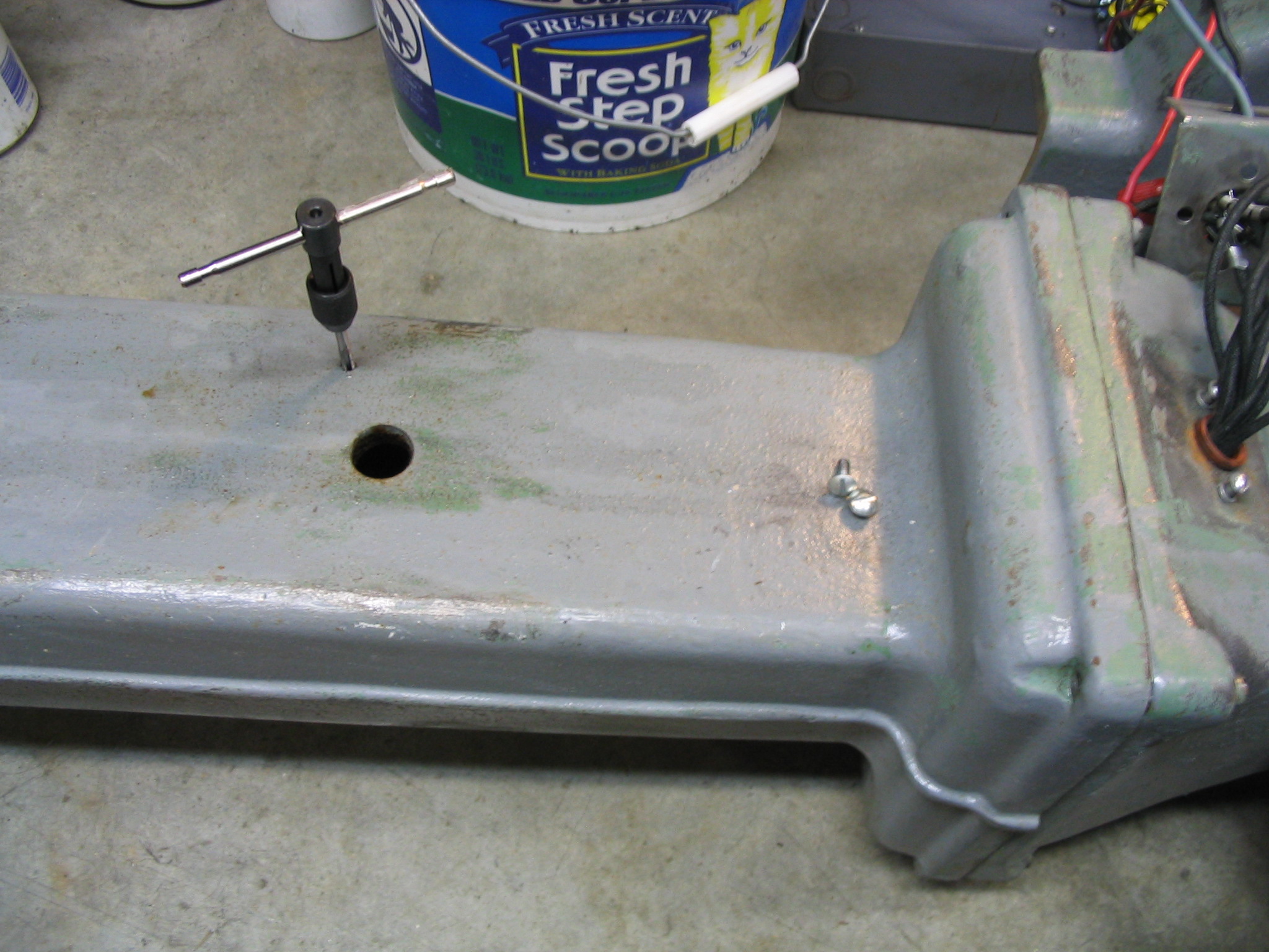
I rewired the relay box to supply single phase power to the phase converter. I attached it to the pedestal stand of the grinder. I drilled holes in the pedestal and tapped screw threads into them, and screwed the relay box in place. Instead of flex conduit for the power line, I added a standard power cord. Since it uses 240 volts, double the US standard, I used a different plug and outlet.
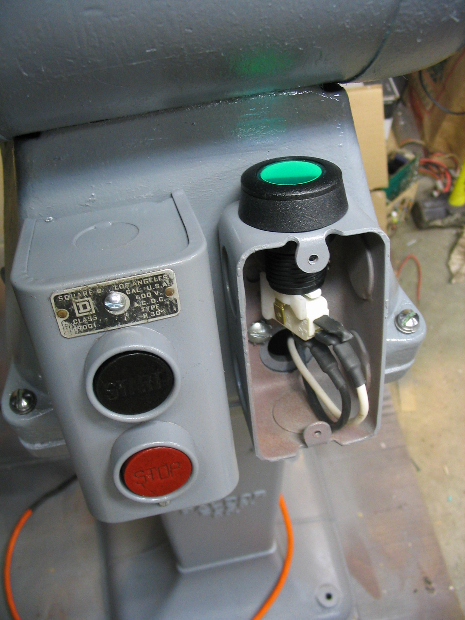
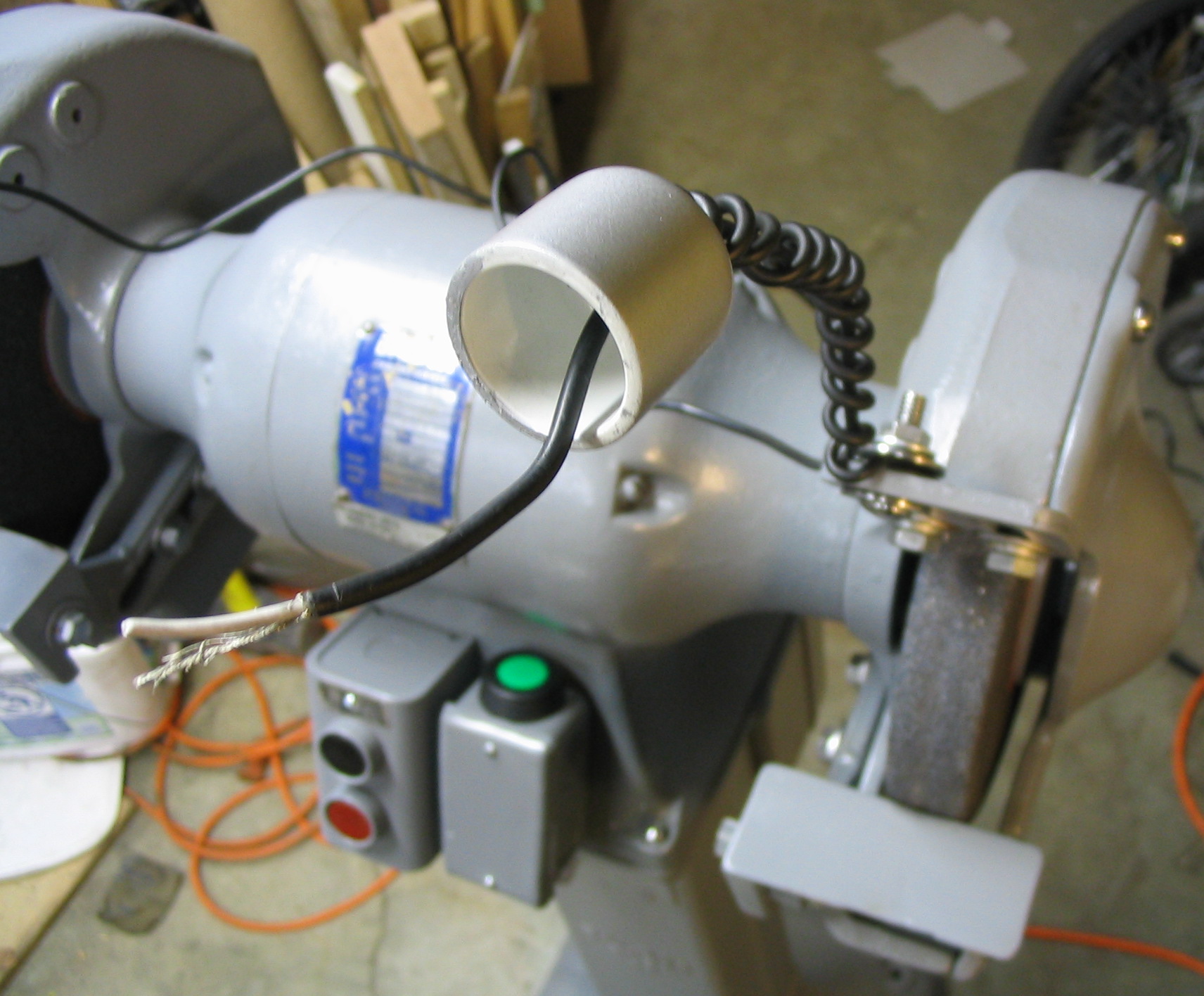
The phase converter needs an extra momentary push button to start the motor, so I added that to the front of the grinder next to the main on-off switch.