I don’t have a very big air compressor. Actually, I have two small air compressors, with not very much power or air capacity. I came across two other air tanks, each slightly larger than the tanks on my existing little compressors. So I figured, what better way to make things work, than a Frankenstein agglomeration of miscellaneous parts? Don’t ask why I figure things that way; I don’t know myself.
One of the extra tanks I bought at a garage sale for $20 (which just about blew my whole project budget right there), and the other I got free from my buddy Rex (who got it from Joe, who got it from somebody else tossing it out I think). The basic idea was to feed both compressors into the pair of tanks, all connected together so that the system would have the combined capacity of all parts. As the philosophers say, “the whole is greater than some of the parts” (or some metaphysical mumbo-jumbo like that; I don’t recall exactly).
Tank You Very Much
Both tanks were originally sold as temporary/portable air storage: fill up at a compressor, then take somewhere else to use for inflating tires or basketballs or blowing pinwheels or whatever. They were made to lay horizontally with welded-on feet to keep them from rolling over. They are not quite the same size as each other but are close; each is a little over 2ft / 60cm long and perhaps 12in / 30cm diameter. The freebie tank came without any fittings, while the garage sale tank came with an air pressure gauge and over-pressure relief valve.
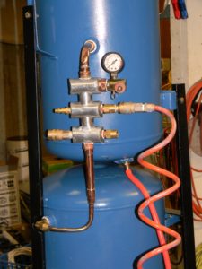
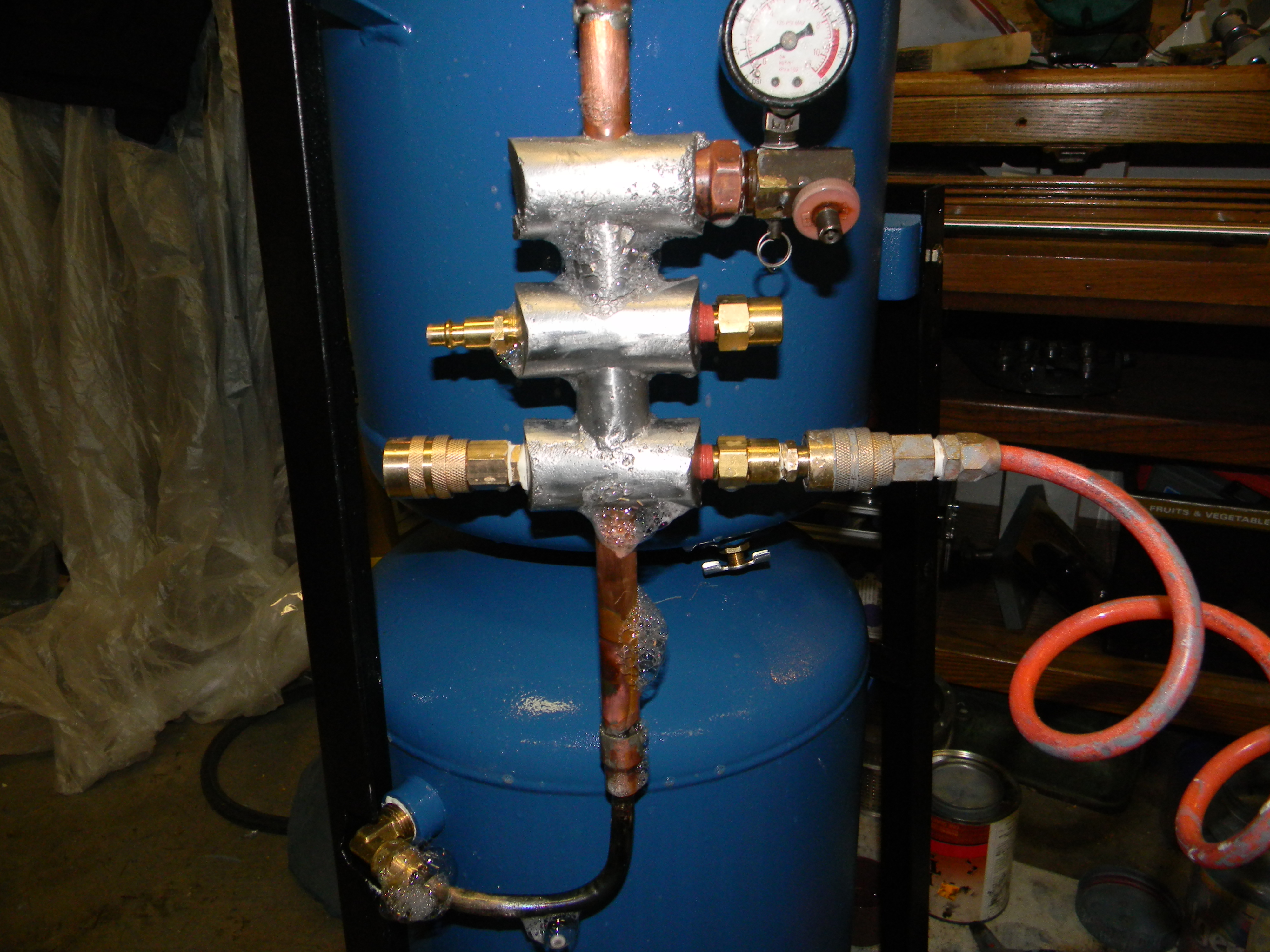
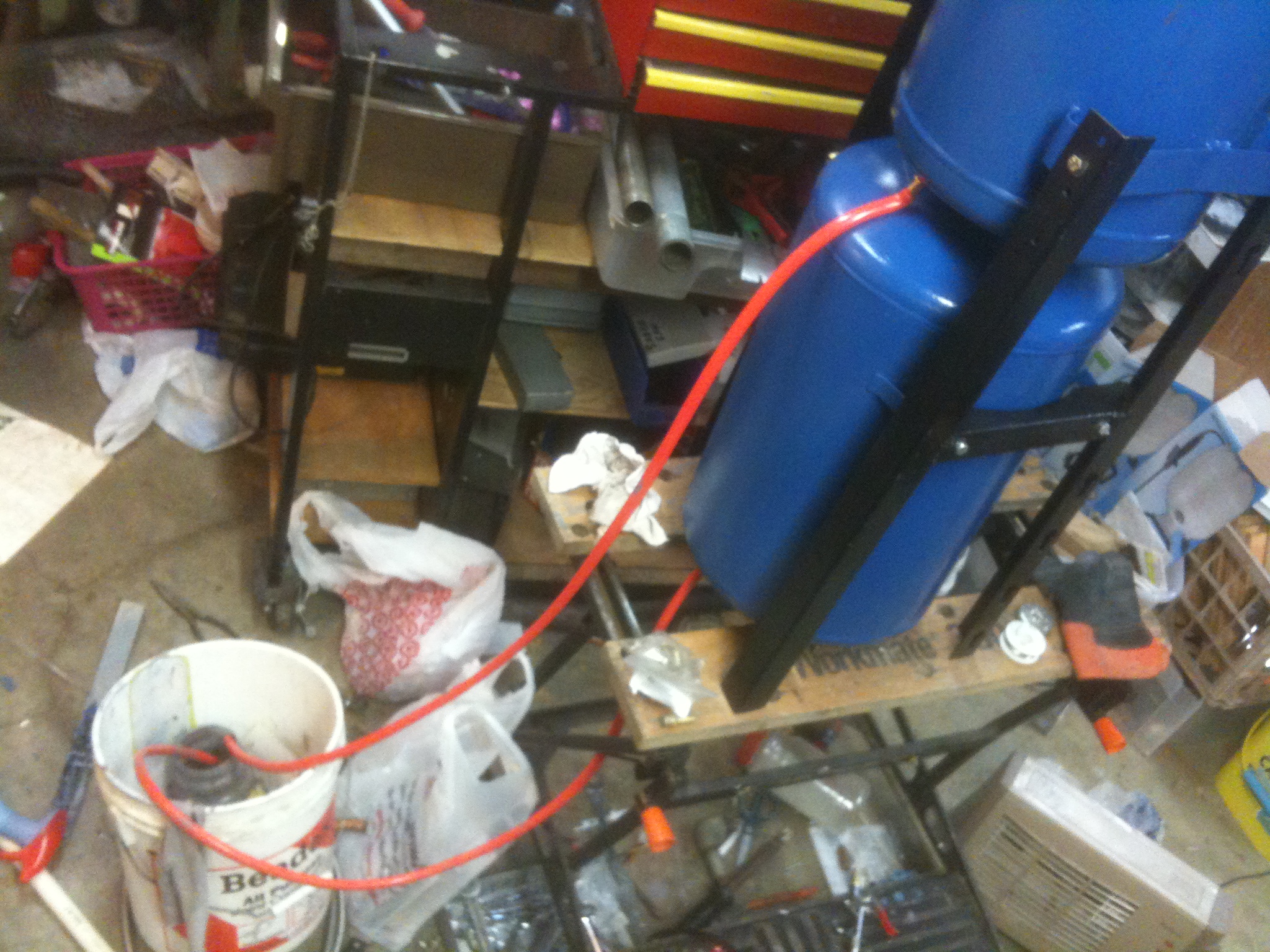
I felt the best way to conserve shop space was to stand them up vertically, one above the other. I used my favorite steel fabrication material (scavenged scrounged repurposed bed frame angle iron) to make a tripod frame and and bolted it to the tank handles and feet, so it all stands upright. I also welded on a small 1/4 inch / 6mm thick steel plate to the bottom of each tank (in the new vertical orientation), and drilled and tapped threads into it, for a draincock valve on each tank. I put them off-center to make them easier to reach, and with the rounded tank ends, they become the low point when the whole thing is tipped forward slightly. If that doesn’t make sense, look at the photos or come over to my house and I’ll show you (assuming you’re not one of those creepy strangers from the Internet, of course).
Manifold Greatness
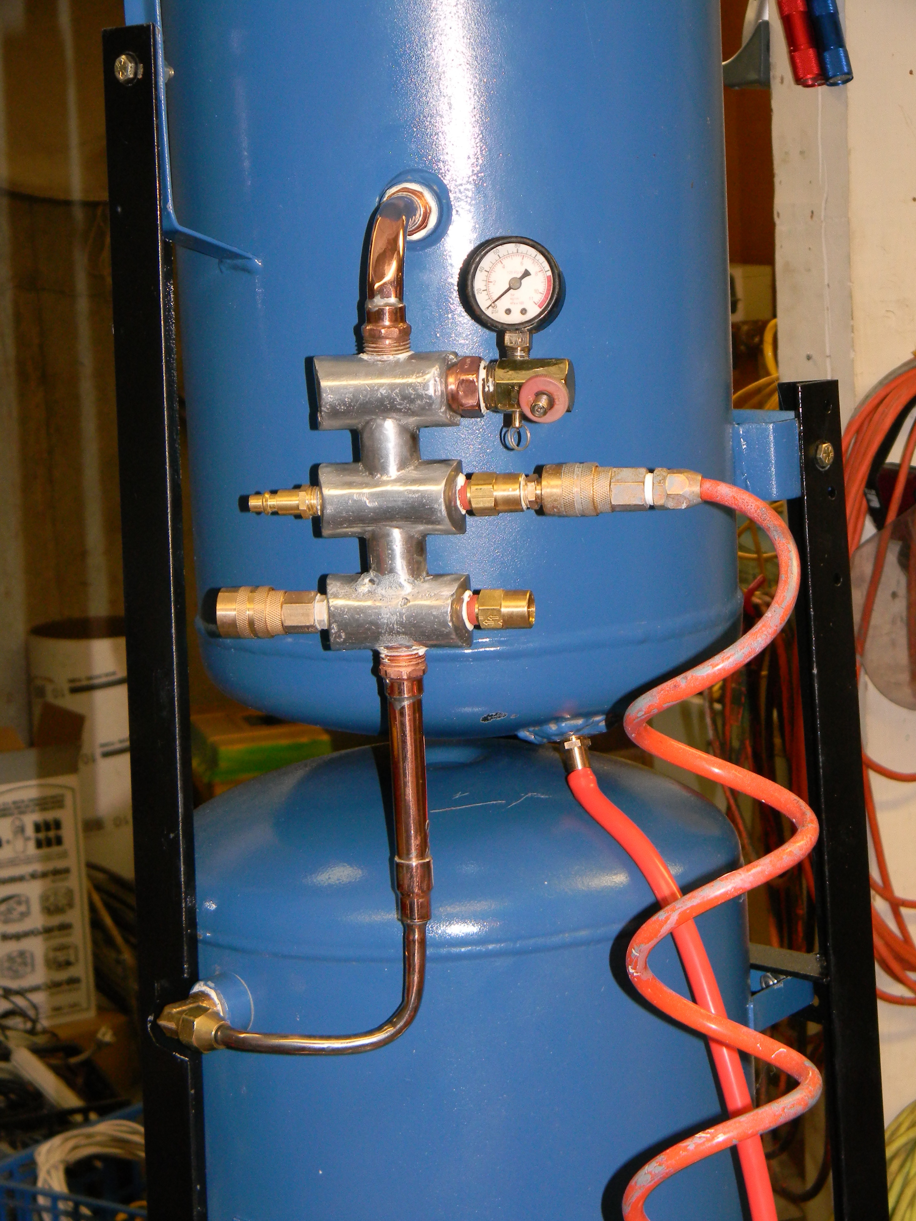
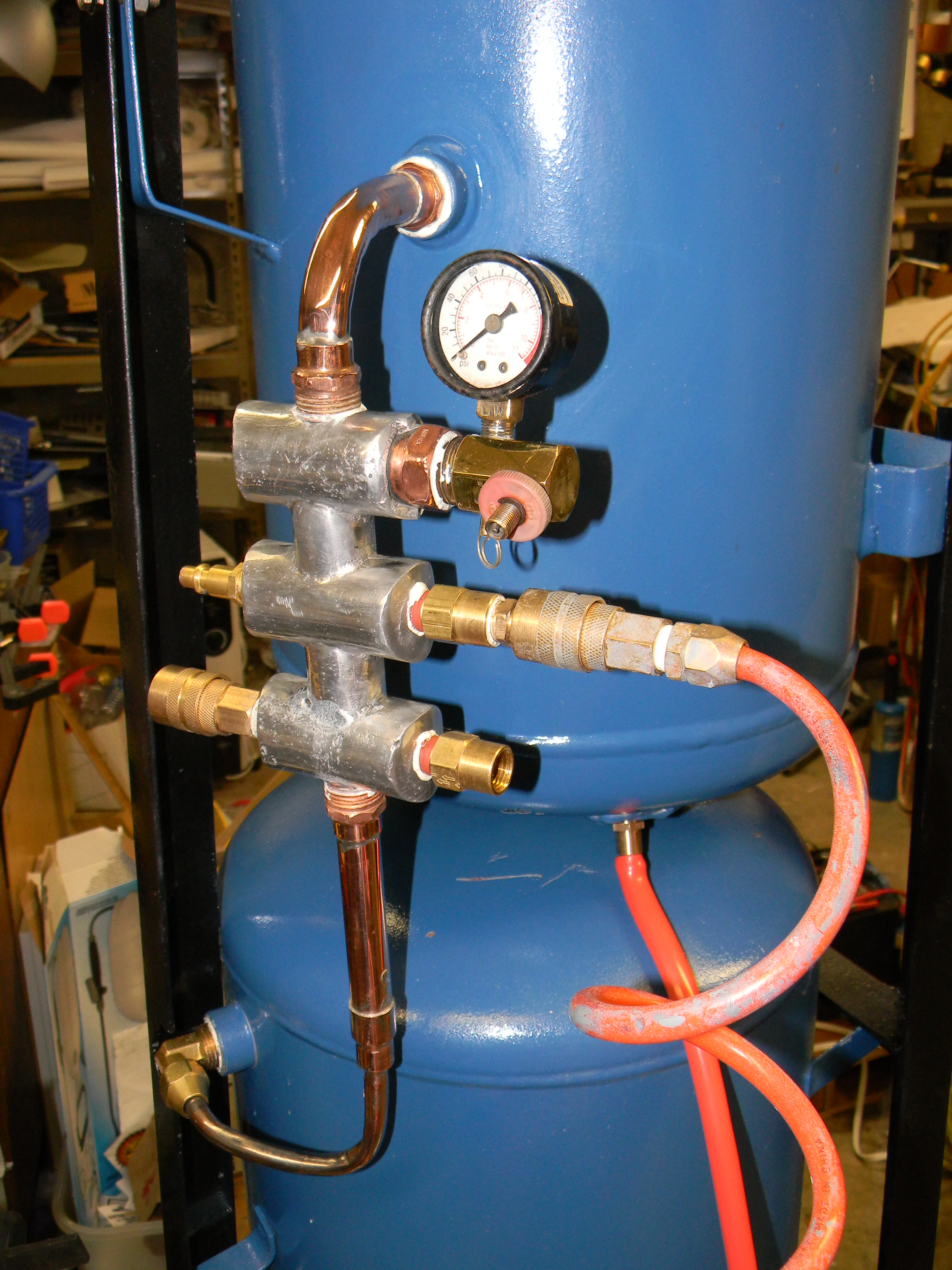
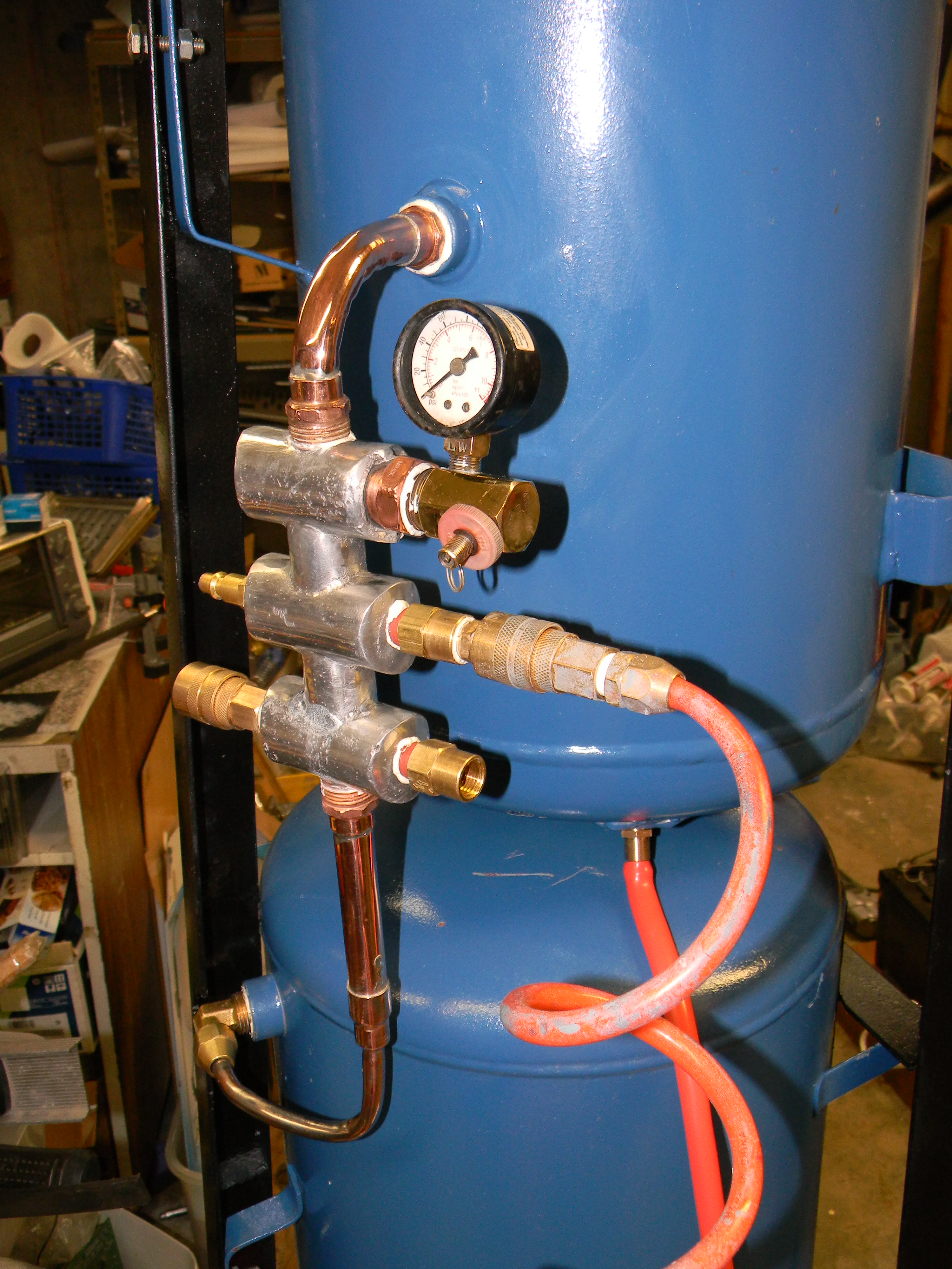
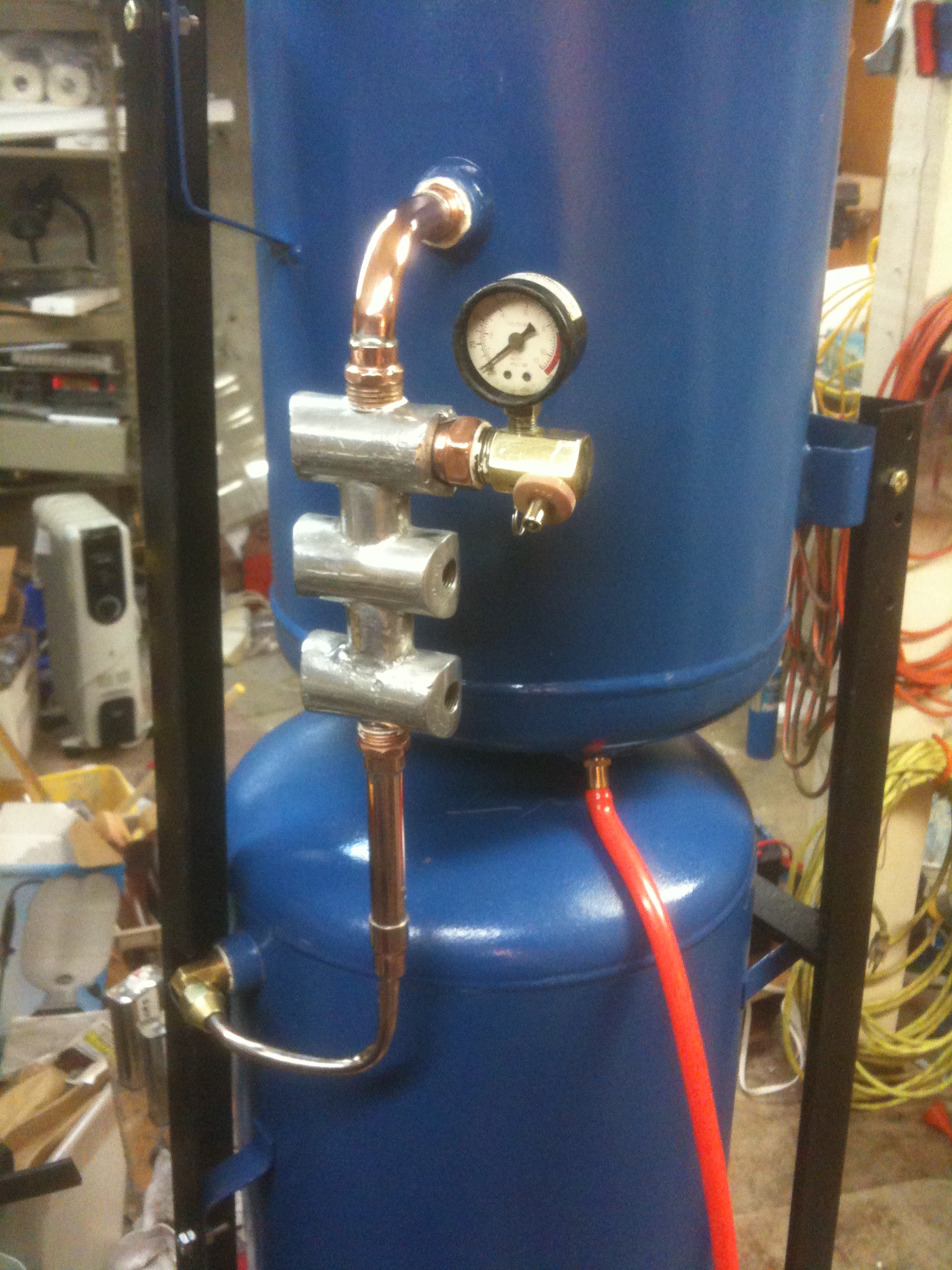
The central connection is a “manifold” with input ports from the compressors, input/output ports to the extra tanks, and one or more final output ports to the air hoses and tools. A manifold is just a pipe or block of metal with multiple ports in it, all connected together, and the ports are just the holes drilled or formed into it. But “manifold” and “port” are much more auspicious sounding names than “pipe” and “hole”, don’t you think? I knew you’d agree.
Dial gauges look cool, and it’s worth keeping the gauge for the geek cred practical troubleshooting value. I can’t imagine how my two little wimpy compressors could overpressure the system (they can barely make 100PSI as it is, chug squeal whine), but safety is always good, so I’ll keep the pressure relief valve too. (Maybe I can figure out how to put a whistle on it; hmm….)
Most compressed air equipment in the U.S. uses the same threaded pipe connections as plumbing pipe, known as National Pipe Tapered (NPT) threads, with pipe sizes named in fractional inches. (Like most things in our last-bastion-of-non-metric-measurement country, these nominal sizes haven’t matched any actual measurements since my grandfather learned to measure pipe diameters by the width of his pinky finger or something like that. Not that I’m bitter about the U.S. measurement system. I learned what a foot and a cup were when I was a toddler, and I still have two feet and a cupboard full of cups, so why would I stop using them now? Really, if a mile and a pound were good enough for the Romans and the Dark Ages, they’re good enough for us too. As Grandpa Simpson said, “My car gets fourty rods to the hogs-head and that’s the way I likes it”. But I digress.) Both air tank openings are 1/2 inch NPT, so it was no problem to make a manifold using off-the-shelf copper pipe plumbing fittings.

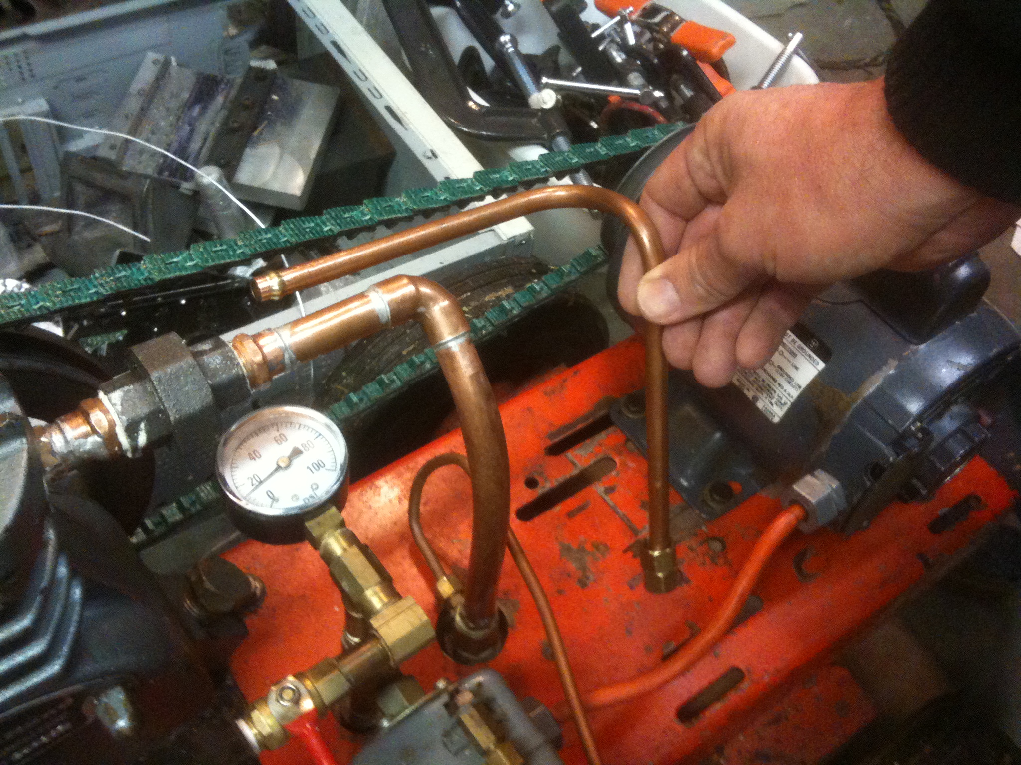
The first version of the manifold was made of a few copper pipe tees, sweat soldered together. The connections to the two tanks were on the ends of the pipe run, and the inline tees provided the two compressor inputs and one hose output (the gauge and relief valve fitting had one input off its side). The two tanks, having threaded NPT openings, presented something of a dilemma on the best way to connect the manifold piping. I could have soldered the pipe solid and spun the tanks on. That would be entertaining on the first assembly, and a royal pain on all subsequent operations. I could have threaded the fittings into the tanks and then soldered the rest together, but that would also be a pain for later disassembly, plus I might melt the teflon tape or pipe dope on the threads. I chose to use a flare nut connection on the lower tank. The manifold is spun into the top tank threads, and then the flare nut secured on the bottom.
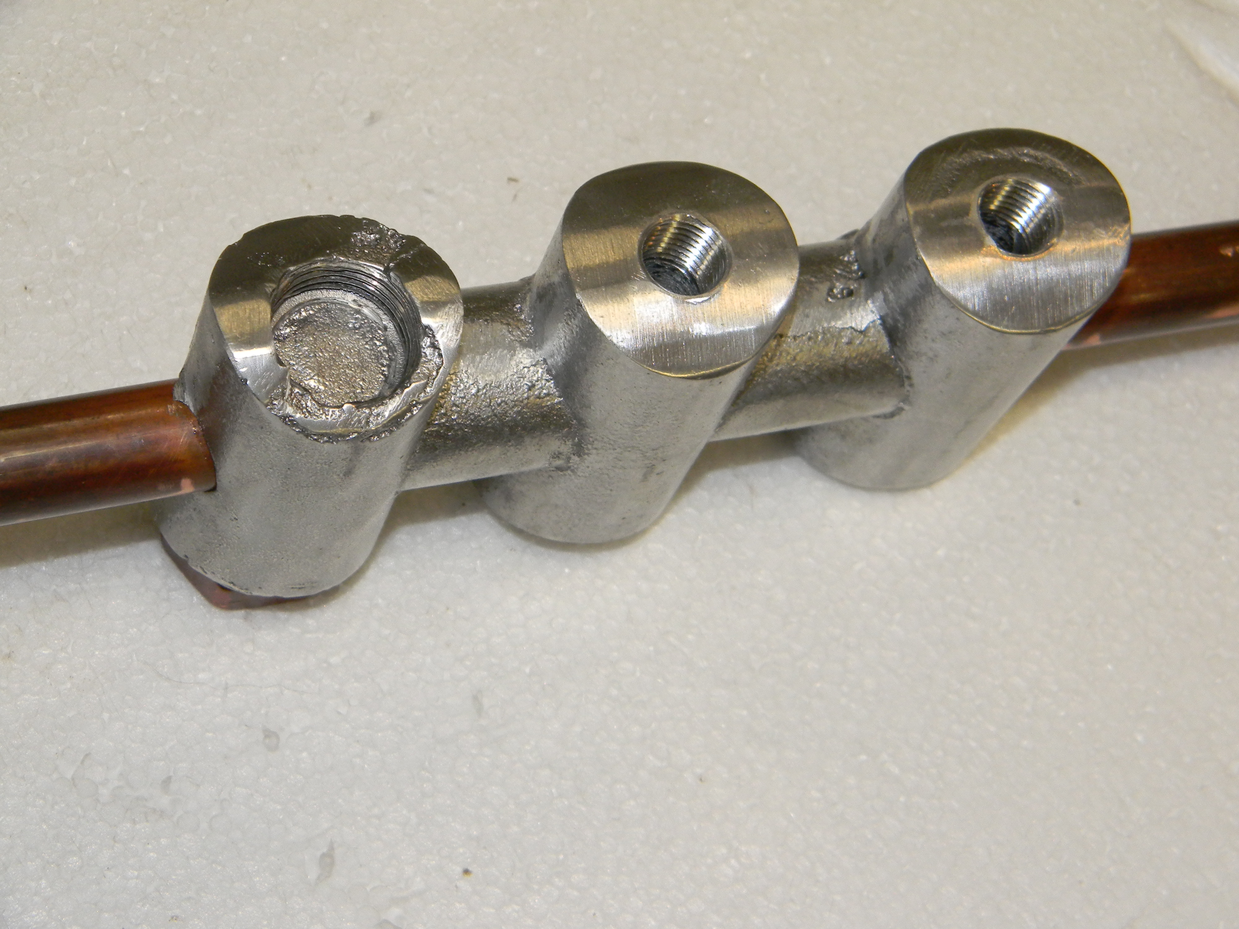
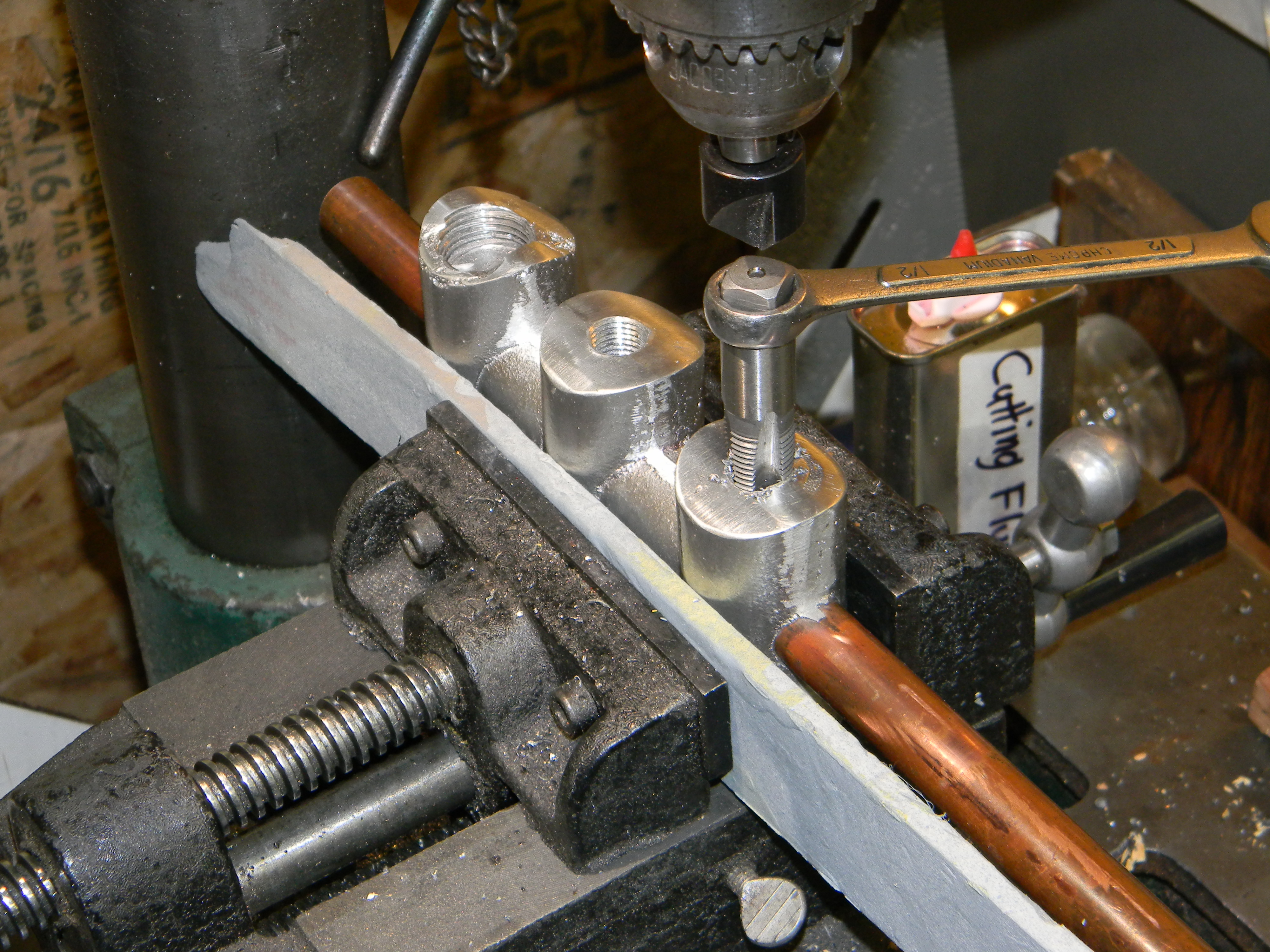
The copper pipe manifold worked adequately, but I only made one output, and I realized I wanted two: one straight out of the tank unrestricted, and one with a pressure regulator. Since the manifold needed a change, this was of course the ideal time to make the project more complicated: instead of soldering in another copper tee, I decided to make an aluminum manifold and cast it in-place around a copper pipe. The common air hose and connector fittings use 1/4 inch NPT threads, and the pressure gauge/valve fitting is 1/2 NPT, so I planned for four of the 1/4 NPT and two of the 1/2 NPT openings.

I made a pattern for it with PVC pipe, and made a sand casting. I put a copper pipe right into the sand mold and poured the aluminum around it, hoping it would stick enough to be air tight. I tried two experiments for the 1/2 NPT ports to pre-make the female threads in the casting. For one, I placed a copper female fitting into the sand mold, and cast it in place alongside the central pipe (I packed the copper fitting with green sand to keep it from filling with molten aluminum). For the other, I packed a short steel 1/2 NPT pipe with green sand, and placed it into the sand mold, in an attempt to mold the threads right in the aluminum around the steel. I covered the steel threads with soot first to reduce sticking, and later managed to unscrew the steel pipe from the cooled casting. I ended up using the copper fitting (drilled through the bottom aluminum into the central pipe) for the gauge/relief valve, and left the cast-in threads for “future expansion”. For the 1/4 NPT ports, I just drilled down into the central pipe and tapped them.
The Pressure Is On
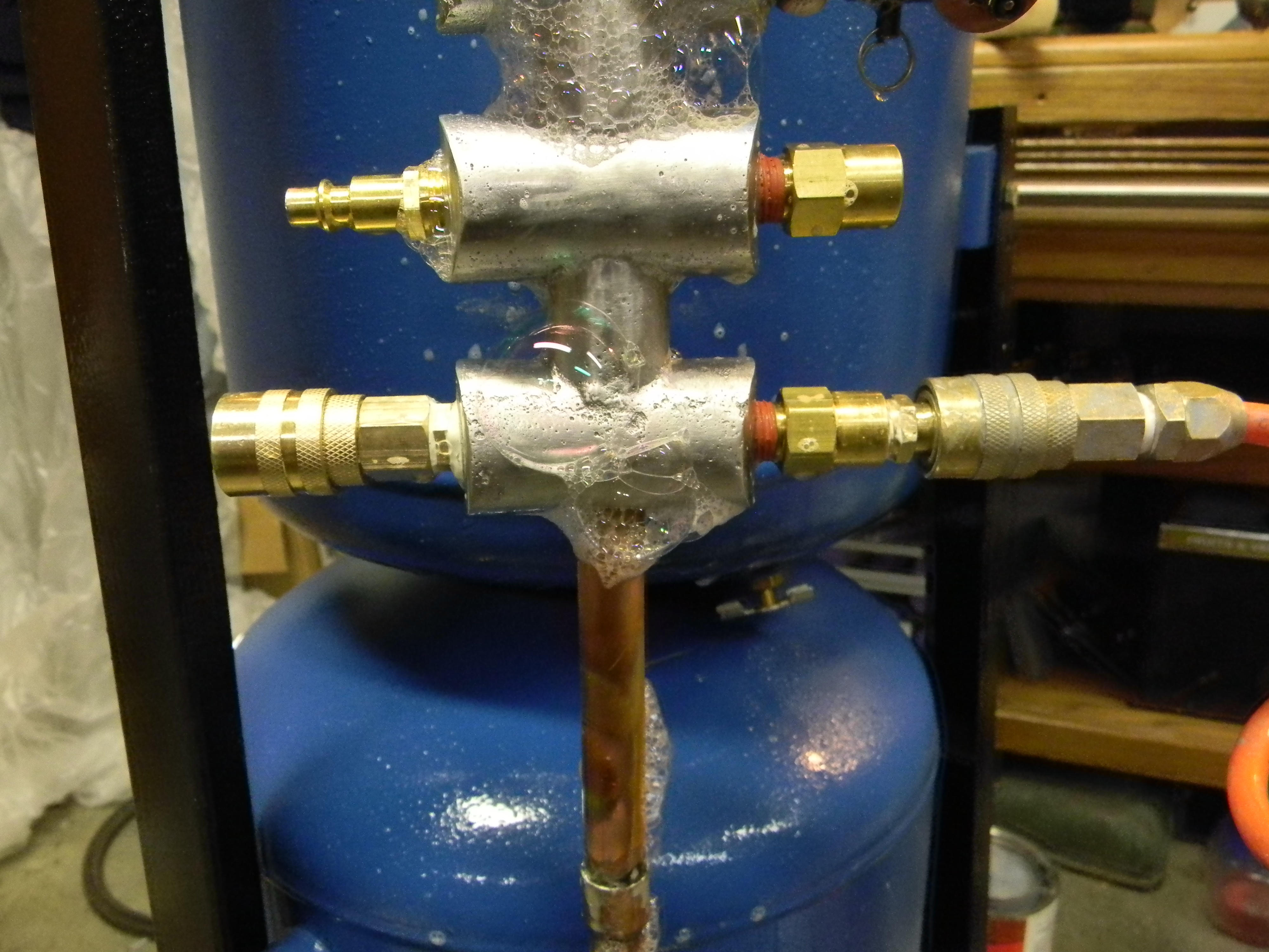
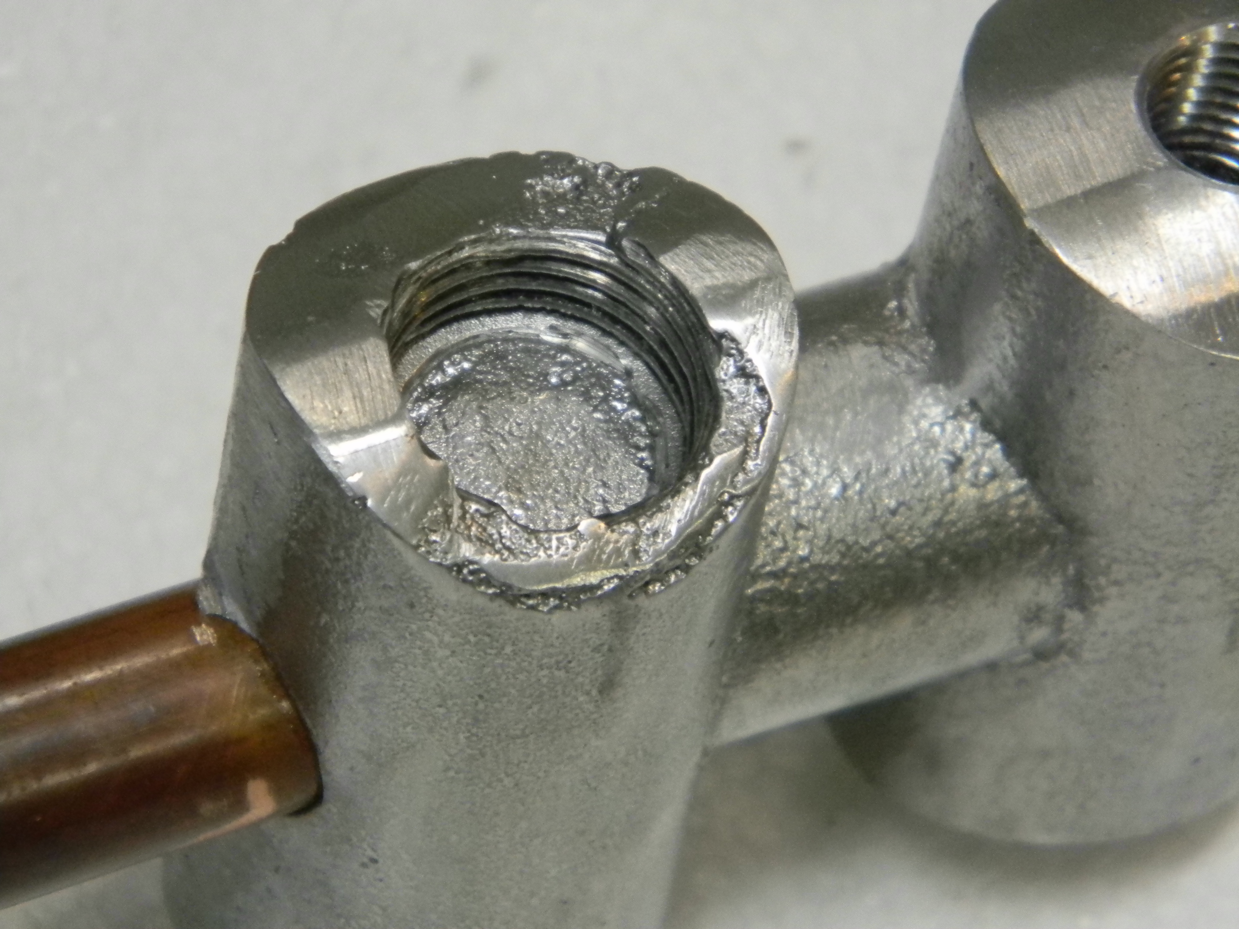
I soldered the central pipe to its end fittings for the tanks, plugged up the ports with air connectors, and tried my first pressure test. I tested for leaks by spraying soapy water on everything, looking for bubbles. I got more than I expected. The manifold leaked out each end around the copper pipe. Not only that, it also leaked right out the middle of the casting! Something bubbled up and left some air pockets in the aluminum when it was poured and then cooled. I’ve seen porosity in cast aluminum before, but usually just individual bubbles here and there, not a complete little tunnel.
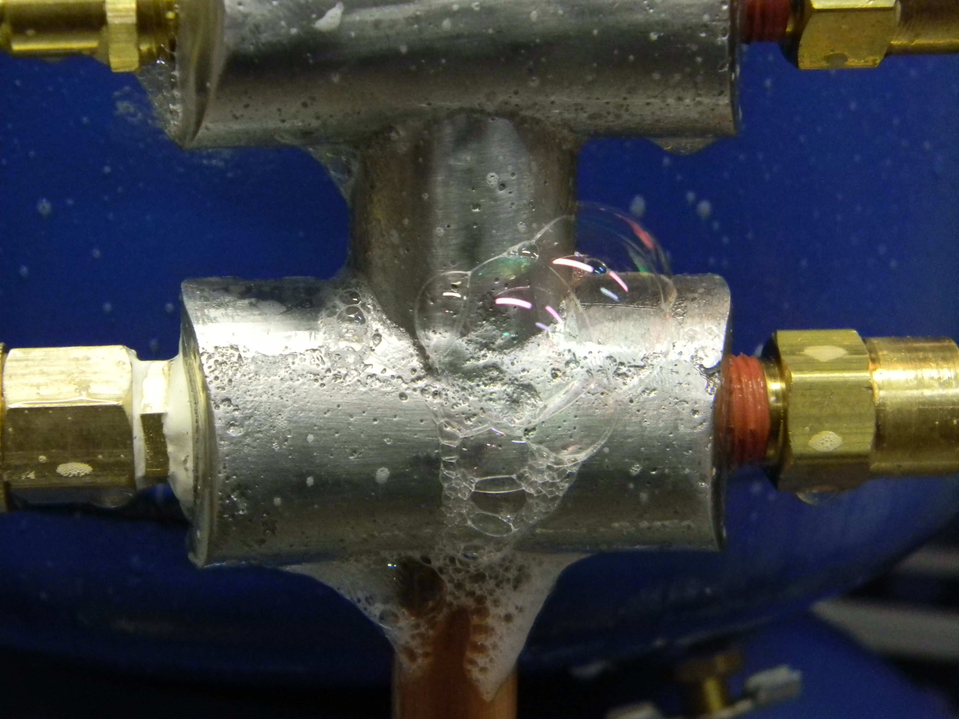
The air leaks around the pipe on each end were interesting also. I didn’t expect the aluminum to fuse with the copper, but I did think it would be gripped tight. That was indeed true; I could not pull the copper pipe from the aluminum casting with any amount of force I had at hand. But it wasn’t quite air tight. I don’t know exactly why, but I know I did not scrub the pipe completely clean or preheat it first. I figure that the hot aluminum hit the cold copper and made it expand slightly, then the aluminum cooled and froze, then the copper cooled and retracted away slightly. It doesn’t take much for air to leak, so that’s my best guess.
The good thing about hobby aluminum sand casting is that nothing is ever a total loss; you can always melt down a bad piece and recast it. But in this case I tried patching it first, just to experiment. I have some “Alumiweld” zinc-based brazing rod which actually works pretty well for soldering aluminum, and it worked properly to fill the porous leak in the center of the casting. I did not have any luck using it to seal the ends of the casting around the copper pipe, which I assume is because I couldn’t get the copper clean enough down in the crack. So I cut off the ends of the pipe, and drilled and tapped 1/2 NPT threads. I made a new elbow for the top tank connection by annealing a piece of 1/2-inch copper pipe (heat to red hot with propane torch), bending it to 90 degrees using coil springs inside and out, and sweat soldering it into two male 1/2 NPT copper fittings. I re-used the lower pipe connection, adding a male 1/2 NPT fitting to thread into the bottom of the manifold.
Spray Paint For The Paint Sprayer
The garage-sale tank was scratched and rusty, and the freebie tank had one or two minor scratches, so they needed a little improvement. I painted them with blue oil paint using my trusty “Critter” siphon spray gun
 See “Critter” siphon spray gun at Amazon.com |
. I love that thing. Fortunately the little compressor put out enough air for it without these tanks; that could have been and interesting bootstrapping dilemma. The Critter works great to spray the used oil paint I got for $1 from the Habitat For Humanity ReStore. I’m sure it works great with better paints, too; I don’t know, I haven’t tried that yet.
Rex, being a smarty-pants, asked if I had painted the insides of the tanks too, to keep rust at bay. And being just as big a smarty-pants as Rex, I thought hey, why not? He had a great list of B.S. creative ways that the insides could be coated with paint. All of them came down to pouring paint in the hole, rotating and swishing around somehow, and dumping the excess. Which is exactly what I did. I skipped the more creative methods suggested by him (such as the motorized gyroscopic rotational assemblage, or airtank inside giant rubber ball bouncing down a hill), and just held each tank and turned it around and over for a few minutes to swish the paint around inside, then poured out the excess. I let the tanks stand on their ends, to let all the excess paint drip down to the drainage hole. After a day they stopped dripping. Then I picked them up and found I did not have the drainage holes at the very bottom and there was still wet paint pooled inside; guess how I found that out? So I leaned them over a little farther and let them finish dripping for an additional day. That worked.
Once no more paint dripped out, it was simlply a matter of attaching the manifold on to them. I blew air through the tanks, in the manifold and out the draincock valves, for a few hours, to vent out the paint fumes.
Final Assembly
The final assembly consisted of installing the petcock drain valves, and adding the connectors on the manifold. I put two one-way check valves on the inputs of the manifold, so neither compressor can be a leakage point, and added quick-connect fittings for the output side. I did a final soap-bubble leakage test, and everything looked good. Success!
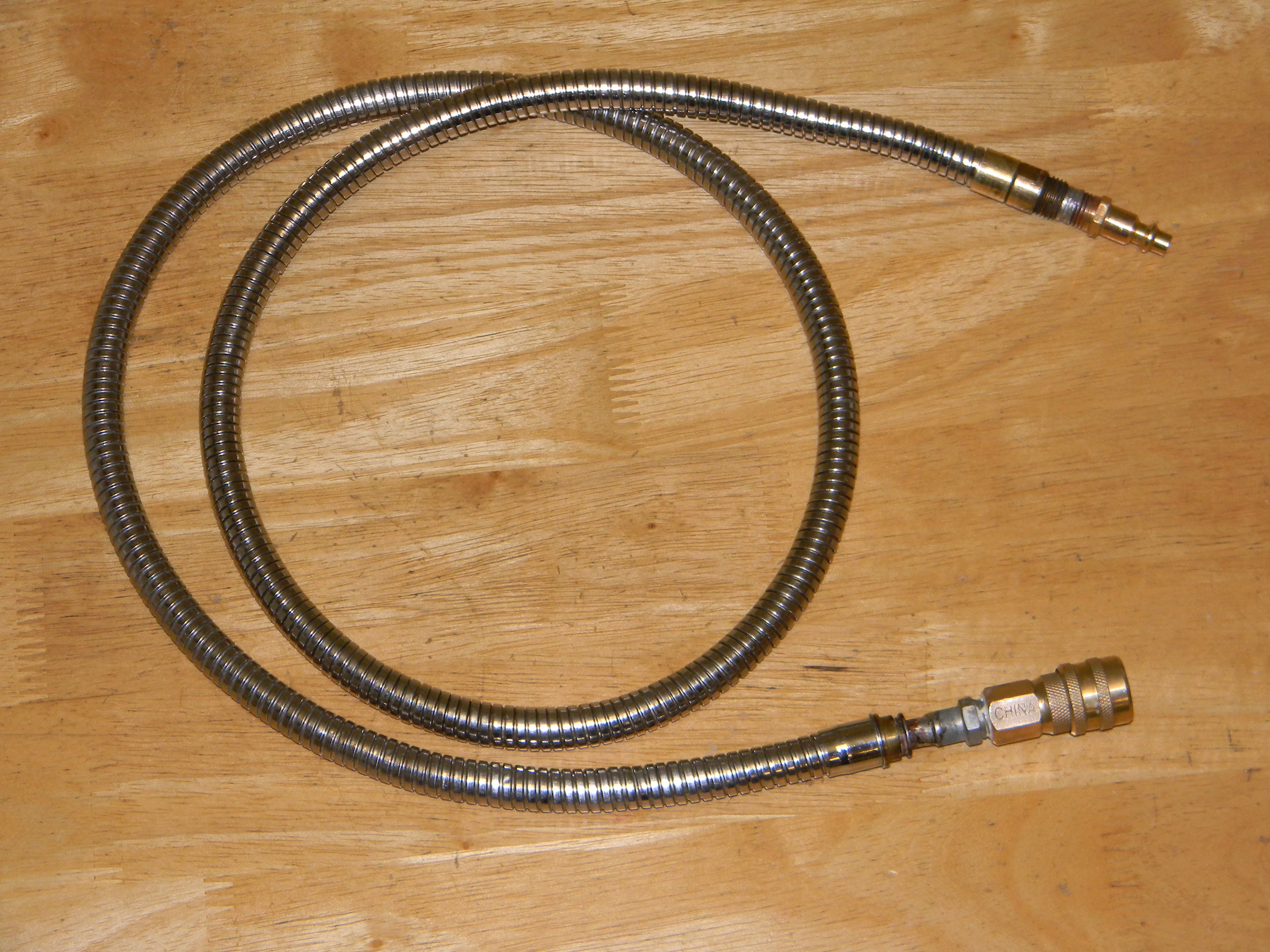 I made an armored air hose. Why? Because I can.